Laminated rechargeable element

a rechargeable element and laminate technology, applied in the direction of cell components, sustainable manufacturing/processing, batteries, etc., can solve the problems of reducing the amount of active materials, corroding of exposed aluminum films, and unable to ensure the necessary discharge capacity, so as to reduce the thickness of the active material, the flatness of the smart card itself is damaged, and the strength can be guaranteed. high

Active Publication Date: 2018-08-09
FDK CORP
View PDF2 Cites 0 Cited by
  • Summary
  • Abstract
  • Description
  • Claims
  • Application Information

AI Technical Summary

Benefits of technology

[0006]The jacket 11 is formed by welding, in thermocompression bonding, the peripheries 12 of two sheets of rectangular, aluminum laminate films 11a, 11b which are stacked, and as a result the inside of the jacket is sealed. As procedures in which the jacket 11 accommodates the electrode assembly 10, the following example is provided: Two facing aluminum laminate films 11a, 11b are shaped into the form of a bag by welding three sides of the rectangle and by leaving the remaining side open; the bag-shaped, aluminum laminate films 11a, 11b accommodate the electrode assembly 10 with the electrolyte; the terminal plates 23, 33 of the positive and negative electrodes 20, 30 protrude beyond the jacket 11 from the opening of the bag-shaped aluminum laminate films 11a, 11b; and the periphery 12 on the opening side is welded, to finish the laminated rechargeable element 1 shown in FIG. 1A. The configuration of a laminated rechargeable element is described, for example, in Japanese Patent Application Publication No. 2006-281613. And, the following document describes the characteristics, discharge performance, etc. of thin lithium cells, which are laminated rechargeable elements: FDK Corporation, “Thin Lithium Primary Batteries”, [online], [searched on Sep. 16, 2015], Internet <URL: http: / / www.fdk.co.jp / battery / lithium / lithium thin.html> (hereinafter referred to as Non Patent Literature (NPL) 1).
[0007]As for a laminated rechargeable element, there is always a demand for reduction in thickness. But, making sheet-shaped positive and negative electrodes thinner leads to reduction in the amount of active material which contributes to discharge, making it impossible to ensure the necessary discharge capacity. Accordingly, the more practical approach is to make the aluminum laminate film constituting the jacket thinner. The aluminum laminate film is covered with resin layers, so that, basically, the laminated cell is provided with a resin layer (hereinafter referred to as a protection layer) for protecting aluminum film against mechanical impact (e.g., piercing, friction, bending). Inside the laminated cell, another resin layer (hereinafter referred to as a welding layer) is provided which is melted by thermocompression bonding at a time of sealing.
[0008]The protection layer of the laminate film will melt as well, in some cases, due to heat at the time of thermocompression bonding. When the protection layer has melted, there is a possibility that the exposed aluminum film is corroded by atmospheric moisture, etc., to produce pinholes. In the case of a rechargeable battery including negative electrode lithium (e.g., a lithium primary battery), when moisture gets inside the rechargeable element through the pinholes, the moisture reacts with lithium to produce hydrogen gas. If a large amount of gas is produced, the thickness of the jacket increases and this makes it impossible to maintain its original external design dimensions. In some cases, welded parts of the peripheries of laminate films are detached, causing leakage. Accordingly, in order to prevent the formation of pinholes, there are limits to how thin the protection layer and the aluminum film can be made. Also, the welding layer cannot be thinner because it is necessary to ensure adhesive strength. Generally speaking, the lower limit of thickness of an aluminum laminate film is about 90 μm, and further reduction in thickness is difficult for conventional laminated rechargeable elements. In particular, as for sheet-shaped information recording media and electronic devices (e.g., smart cards, Integrated Circuit tags; hereinafter collectively referred to as a smart card) described in NPL 1 and the like, laminated rechargeable elements which are built into such media and devices have an extremely thin thickness of less than 1 mm, and the jacket and all other components of these rechargeable elements are made as thin as possible. Thus, it can be said that reduction in thickness has reached a limit.
[0009]Conceivably, a stainless steel laminate film whose substrate is stainless steel could be used for a jacket instead of an aluminum laminate film whose substrate is aluminum film. As is well known, stainless steel is a material that is largely corrosion-proof, and therefore even when being thinner than aluminum film, high strength can be ensured. But, stainless steel is a hard material. So, unlike aluminum laminate film, which is flexible, stainless steel laminate film cannot be restored to its original shape once it has been bent or twisted. If the shape is forcibly restored by exerting an external force on it, the bent portions become creased and remain creased. If, for example, a laminated rechargeable element built into a smart card is creased, this damages the flatness of the smart card itself, making the creased portions thicker. The thicknesses of the smart cards is strictly specified by standard, and therefore creases of the laminated rechargeable element makes it impossible to insert the smart card into a smart card slot of an electronic device. If such a smart card is forcibly inserted, there is a possibility that the smart card cannot be removed.
[0010]In laminated rechargeable elements including those for smart cards, when creases occur in the jacket surface, each such crease has a shape in which its top is bent sharply. When the top of such a crease comes into contact with the electrode assembly inside the jacket, the following phenomena will occur: Partial contact faults occur between the current collector and the electrode; deformation of an electrode makes discharge unstable; and internal short-circuits occur. In some cases, it could also cause a substantial reduction of discharge capacity (a phenomenon called “discharge shortfall”) in which discharge becomes impossible at a time of discharging an amount considerably smaller than the design capacity. Conceivably, by replacing the electrolyte with high-viscosity polymer electrolyte, the jacket is supported from the inside of the rechargeable element to make the jacket difficult to bend. But, since the ionic conductance of polymer electrolyte is lower than that of the electrolyte, a laminated rechargeable element using polymer electrolyte cannot achieve sufficient discharge performance. In particular, in the case of a laminate-film rechargeable element whose thickness is as small as possible so that it can be built into the foregoing smart card, components contributing to discharge (e.g., current collector, electrodes) are as thin as possible to maintain discharge performance. Accordingly, it is actually impossible to further lower discharge performance.
[0011]According to this disclosure, an improved laminated rechargeable element includes a jacket and an electrode assembly. The jacket is formed of two flat, rectangular stainless steel laminate films welding together at their peripheries. The electrode assembly includes a sheet-shaped positive electrode, a sheet-shaped negative electrode, and a separator interposed between the positive electrode and the negative electrode, the electrode assembly accommodated in the jacket together with an electrolyte. The separator includes an ion-permeable substrate and ion-permeable bonding layers formed on a top surface and a bottom surface of the substrate. The positive electrode and the negative electrode are welded to respective bonding layers of the separator. The jacket is welded to the electrode assembly.

Problems solved by technology

But, making sheet-shaped positive and negative electrodes thinner leads to reduction in the amount of active material which contributes to discharge, making it impossible to ensure the necessary discharge capacity.
When the protection layer has melted, there is a possibility that the exposed aluminum film is corroded by atmospheric moisture, etc., to produce pinholes.
If a large amount of gas is produced, the thickness of the jacket increases and this makes it impossible to maintain its original external design dimensions.
In some cases, welded parts of the peripheries of laminate films are detached, causing leakage.
Accordingly, in order to prevent the formation of pinholes, there are limits to how thin the protection layer and the aluminum film can be made.
Also, the welding layer cannot be thinner because it is necessary to ensure adhesive strength.
Generally speaking, the lower limit of thickness of an aluminum laminate film is about 90 μm, and further reduction in thickness is difficult for conventional laminated rechargeable elements.
But, stainless steel is a hard material.
So, unlike aluminum laminate film, which is flexible, stainless steel laminate film cannot be restored to its original shape once it has been bent or twisted.
If the shape is forcibly restored by exerting an external force on it, the bent portions become creased and remain creased.
If, for example, a laminated rechargeable element built into a smart card is creased, this damages the flatness of the smart card itself, making the creased portions thicker.
The thicknesses of the smart cards is strictly specified by standard, and therefore creases of the laminated rechargeable element makes it impossible to insert the smart card into a smart card slot of an electronic device.
If such a smart card is forcibly inserted, there is a possibility that the smart card cannot be removed.
When the top of such a crease comes into contact with the electrode assembly inside the jacket, the following phenomena will occur: Partial contact faults occur between the current collector and the electrode; deformation of an electrode makes discharge unstable; and internal short-circuits occur.
In some cases, it could also cause a substantial reduction of discharge capacity (a phenomenon called “discharge shortfall”) in which discharge becomes impossible at a time of discharging an amount considerably smaller than the design capacity.
But, since the ionic conductance of polymer electrolyte is lower than that of the electrolyte, a laminated rechargeable element using polymer electrolyte cannot achieve sufficient discharge performance.
Accordingly, it is actually impossible to further lower discharge performance.

Method used


Image

  • Laminated rechargeable element
  • Laminated rechargeable element
  • Laminated rechargeable element

Examples


Embodiment Construction

[0017]In describing embodiments illustrated in the drawings, specific terminology is employed for the sake of clarity. However, the disclosure of this patent specification is not intended to be limited to the specific terminology so selected, and it is to be understood that each specific element includes all technical equivalents that have the same function, operate in a similar manner, and achieve a similar result.

[0018]Referring now to the drawings, wherein like reference numerals designate identical or corresponding parts throughout the several views thereof, a laminated rechargeable element according to embodiments of the present disclosure are described. As used herein, the singular forms “a”, “an”, and “the” are intended to include the plural forms as well, unless the context clearly indicates otherwise.

[0019]Structure

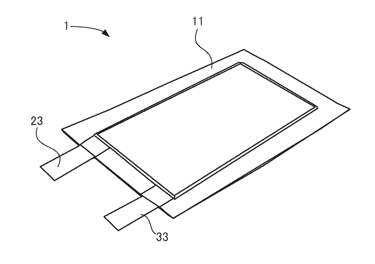
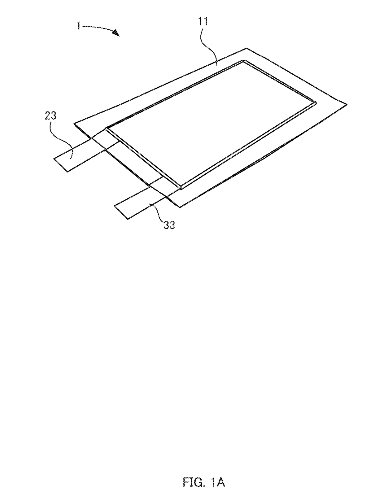
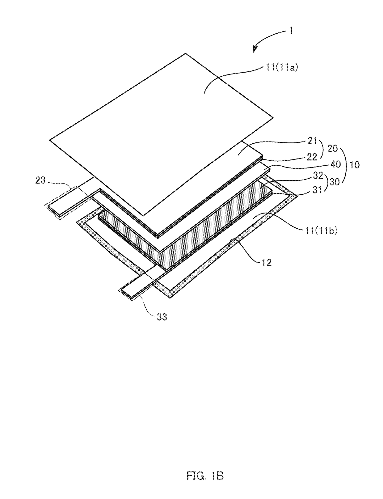
[0020]FIGS. 2A and 2B show the structure of a laminated rechargeable element according to an embodiment of this disclosure (hereinafter also referred to as a rec...


PUM

PropertyMeasurementUnit
thicknessaaaaaaaaaa
thicknessaaaaaaaaaa
thicknessaaaaaaaaaa

Abstract

A laminated rechargeable element includes a jacket and an electrode assembly. The electrode assembly is accommodated in the jacket together with an electrolyte, and includes a separator, a sheet-shaped positive electrode and a sheet-shaped negative electrode. The electrode assembly is formed by laminating the positive electrode and the negative electrode with the separator interposed between the positive electrode and the negative electrode. The separator includes an ion-permeable substrate and ion-permeable bonding layers formed on a top surface and a bottom surface of the substrate. The positive electrode and the negative electrode are welded to respective bonding layers of the separator. The jacket is formed of two flat, rectangular stainless steel laminate films welding together at their peripheries, and is welded to the electrode assembly.

Description

CROSS-REFERENCE TO RELATED APPLICATIONS[0001]This patent application is a continuation of International Application PCT / JP2016 / 079867, with an international filing date of Oct. 6, 2016, which in turn claims priority to Japanese Patent Application No. 2015-198151, filed on Oct. 6, 2015 in the Japan Patent Office, the entire disclosures of which are hereby incorporated by reference herein.TECHNICAL FIELD[0002]This disclosure relates to a laminated rechargeable element including the jacket which is made of laminate film and which accommodates a power-generating element.BACKGROUND ART[0003]In recent years, various thin electronic devices have come into practical use, for example, electronic paper, Integrated Circuit tags, smart cards, electronic keys or the like. As power sources for such thin electronic devices, laminated rechargeable elements (e.g., primary cells, secondary cells, electric double-layer capacitors), which can be made thin and small, are often used. Even for large-capac...

Claims


Application Information

Patent Timeline
Patent Type & Authority Applications(United States)
IPC IPC(8): H01M10/0585H01G11/24H01G11/52H01G11/58H01G11/78H01G11/84H01M2/16H01M2/02H01M50/105H01M50/119H01M50/417H01M50/426H01M50/457H01M50/55H01M50/557
CPCH01G11/84H01M2/168H01M2/1653H01M2/0267H01M2/0207H01M10/0585H01G11/24H01G11/52H01G11/58H01G11/78H01M10/052H01M2220/30H01G11/82Y02E60/10H01M50/557H01M50/124H01M50/461Y02P70/50H01M50/417H01M50/105H01M50/55H01M50/457H01M50/426H01M50/119
Inventor MANO, TSUKASANISHIMURA, NAOAKIIIDA, YUYAITO, RYUJI
Owner FDK CORP
Why Eureka
Try Eureka