Self-balanced pressure hull device

a pressure hull and self-balancing technology, which is applied in the field of submersibles, can solve the problems of difficult elimination or reduction of pressure hull vibration, complicated structure of the whole control system, and high energy consumption of control methods, and achieves relatively balanced and stable inner housing, reduced axial impact, and reduced horizontal and vertical vibrations.

Active Publication Date: 2018-08-23
JIANGSU UNIV OF SCI & TECH
View PDF0 Cites 20 Cited by
  • Summary
  • Abstract
  • Description
  • Claims
  • Application Information

AI Technical Summary

Benefits of technology

[0021](1) With reference to a structural principle of a two-axis gyroscope, the self-balanced pressure hull device of the present invention has a three-layer structure. The outermost housing is equivalent to an outer frame of the gyroscope, the intermediate housing is equivalent to a gimbal of the gyroscope, and the inner housing is equivalent to the inner frame of the gyroscope. The three housings are mutually connected by using two groups of rotary shafts, and an axis of the rotary shafts between the inner layer and the intermediate layer is perpendicular to that of the rotary shafts between the intermediate layer and the outer layer. By use of such a three-layer rotary hull structure in the mode of a two-axis gyroscope, the horizontal and vertical vibrations of the outer housing have been greatly reduced after being transferred to the inner housing, thus maintaining the inner housing relatively balanced and stable.
[0022]Ends of the shafts in the two groups are each mounted with a spring, which can reduce an axial impact between each two adjacent housings and resist relative rotation. Because a spring damper is added on each of connecting shafts between adjacent housings, the vibration of the outer housing along the horizontal direction has been greatly reduced after being transferred to the inner housing under the effect of the intermediate housing and the springs.
[0023]A self-

Problems solved by technology

However, various instruments and apparatuses carried in the submersible generally need to operate under normal pressure and temperature, and survival conditions of submerged members further need to approach those on land.
(1) The deep-sea submersible greatly vibrates under complicated underwater conditions, thus greatly affecting stable operations of various instruments and apparatuses, and the working environment of researchers. An existing submersible mainly uses a relatively complicated negative feedback closed-loop control system to control multiple groups of propellers disposed around the submersible, to adjust the posture of the submersible and reduce the vibration. However, such a control manner needs to consume a lot of energy, and the whole control system has a complicated structure and low reliability. For a single-layer pressure hull, even after a counterweight is added to the bottom, it is still difficult to eliminate or reduce the vibration of the pressure hull caused by the flow of the external sea water.
(2) For the deep-sea submersible, the pressure hull withstands a high external water pressure. If a conventional single-layer pressure hull is used, a high-strength material needs to be used or the

Method used


Image

  • Self-balanced pressure hull device
  • Self-balanced pressure hull device
  • Self-balanced pressure hull device

Examples


Embodiment Construction

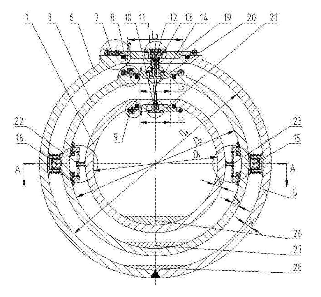
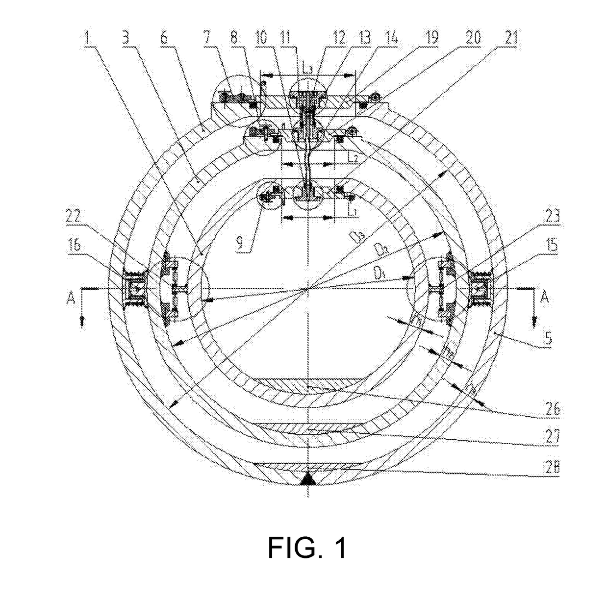
[0047]The working principle, connection, and assembly of a self-balanced pressure hull device of the present invention is described in detail below with reference to FIG. 1 to FIG. 15 of the patent.

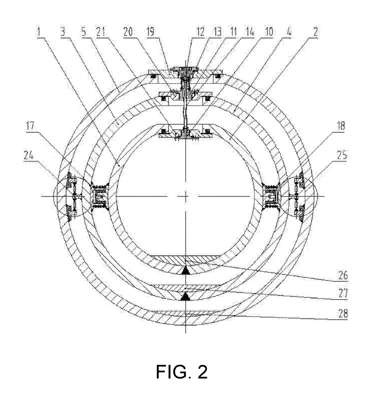
[0048]As shown in FIG. 2 to FIG. 9, the present invention is assembled by successively nesting, from inside to outside, a spherical inner housing, a spherical intermediate housing and a spherical outer housing around the sphere centre. The spherical inner housing and the spherical intermediate housing, as well as the spherical intermediate housing and the spherical outer housing, are axially connected via a pair of slide bearings. Two axes are mutually perpendicular, such that the spherical inner housing and the spherical intermediate housing, as well as the spherical intermediate housing and the spherical outer housing, can rotate relative to each other. Each of the connecting shafts in the two pairs is provided with a spring damper at the outside, for resisting an axial impact between e...


PUM


Abstract

A self-balanced pressure hull device, belonging to the field of pressure structure technology of deep-sea submersibles, being assembled by nesting, from inside to outside, a spherical inner housing, a spherical intermediate housing and a spherical outer housing around the sphere centre, pairs of symmetric coaxial connecting shaft components being connected between the spherical inner housing and the spherical intermediate housing and between the spherical intermediate housing and the spherical outer housing, respectively; axes of the two pairs of connecting shaft components are perpendicular to each other so as to enable the spherical inner housing and the spherical intermediate housing to rotate relative to each other, and the spherical intermediate housing and the spherical outer housing to rotate relative to each other; and each of the connecting shaft components in the two pairs being provided with a spring damper for resisting the axial impact between each two adjacent housings.

Description

BACKGROUNDTechnical Field[0001]In the technical field of submersibles, the present invention relates to a pressure structure of a deep-sea submersible, and in particular, to a self-balanced pressure hull device of three layers in a pressure decline mode.Description of Related Art[0002]As the speed of ocean development continues to accelerate, the depth of exploration from offshore to distant sea constantly increases. Submersibles with various functions are of a great variety and develop rapidly, which are mainly applied in marine resource exploration and development, scientific research, military exploration, salvage, and other aspects. A submersible is important equipment for ocean exploration and deep-sea scientific research. As a crucial part of the submersible, a pressure hull is used to guarantee normal operation of internal apparatuses and health and safety of the crew in a diving process. The weight thereof accounts for ¼ to ½ of the total weight of the submersible. The desig...

Claims


Application Information

Patent Timeline
IPC IPC(8): B63B3/13B63G8/24B63G8/00
CPCB63B3/13B63G8/24B63G8/001B63G8/26
Inventor ZHANG, JIANZHOU, TONGTANG, WENXIANZHANG, WEIGUANGDAI, MIGEZHANG, BINGFENG, SAISAISU, SHIJIEZHANG, BEN
Owner JIANGSU UNIV OF SCI & TECH
Why Eureka
Try Eureka