Compound for metal powder injection molding, metal powder molded body, method for producing sintered body, and sintered body

Active Publication Date: 2018-08-30
SEIKO EPSON CORP
View PDF1 Cites 2 Cited by
  • Summary
  • Abstract
  • Description
  • Claims
  • Application Information

AI Technical Summary

Benefits of technology

The invention provides a sintered body that has both high mechanical strength and ductility. The patent also provides a method for producing the sintered body, a compound for metal powder injection molding, and a metal powder molded body that can produce such a sintered body.

Problems solved by technology

Conventional metal sintered bodies do not sufficiently meet this market demand.

Method used


Image

  • Compound for metal powder injection molding, metal powder molded body, method for producing sintered body, and sintered body
  • Compound for metal powder injection molding, metal powder molded body, method for producing sintered body, and sintered body
  • Compound for metal powder injection molding, metal powder molded body, method for producing sintered body, and sintered body

Examples


example 1

Production of Secondary Particles

[0226]First, as first metal particles, an austenitic stainless steel powder (SUS316L) having an average particle diameter of 10 μm produced by a water atomization method was prepared.

[0227]On the other hand, as a binder, polyvinyl alcohol (PVA-117, manufactured by Kuraray Co., Ltd.) was prepared. Further, as a solvent, ion exchanged water was prepared. The additional amount of the solvent was set to 50 g per g of the binder.

[0228]Subsequently, polyvinyl alcohol was mixed with ion exchanged water, and the resulting mixture was cooled to room temperature, whereby a binder solution was prepared. The mixing ratio of the binder to the first metal particles is as shown in Table 1.

[0229]Subsequently, the first metal particles and the binder solution were mixed, whereby a slurry was prepared.

[0230]Subsequently, the slurry was placed in a spray dryer and granulated, whereby secondary particles having an average particle diameter of 75 μm were obtained.

Produ...

example 2

Production of Secondary Particles

[0239]First, secondary particles were obtained in the same manner as in Example 1.

Production of Granulated Particles for Matrix Region

[0240]Subsequently, as second metal particles, an austenitic stainless steel powder (SUS316L) having an average particle diameter of 4 μm produced by a water atomization method was prepared.

[0241]On the other hand, as a binder, polyvinyl alcohol (PVA-117, manufactured by Kuraray Co., Ltd.) was prepared. Further, as a solvent, ion exchanged water was prepared. The additional amount of the solvent was set to 50 g per g of the binder.

[0242]Subsequently, polyvinyl alcohol was mixed with ion exchanged water, and the resulting mixture was cooled to room temperature, whereby a binder solution was prepared.

[0243]Subsequently, the second metal particles and the binder solution were mixed, whereby a slurry was prepared.

[0244]Subsequently, the slurry was placed in a spray dryer and granulated, whereby granulated particles for t...

example 3

[0250]A sintered body was obtained in the same manner as in Example 1 except that the heating treatment was performed by placing the obtained secondary particles in a heating furnace. The conditions for the heating treatment are as follows.

Heating Conditions

[0251]Heating temperature: 500° C.[0252]Heating time: 60 minutes[0253]Heating atmosphere: nitrogen atmosphere


PUM

PropertyMeasurementUnit
Fractionaaaaaaaaaa
Fractionaaaaaaaaaa
Fractionaaaaaaaaaa

Abstract

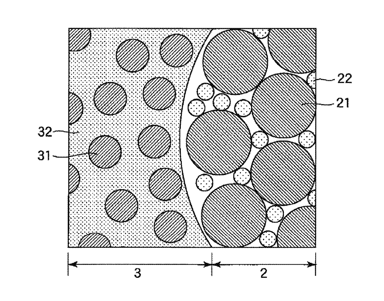
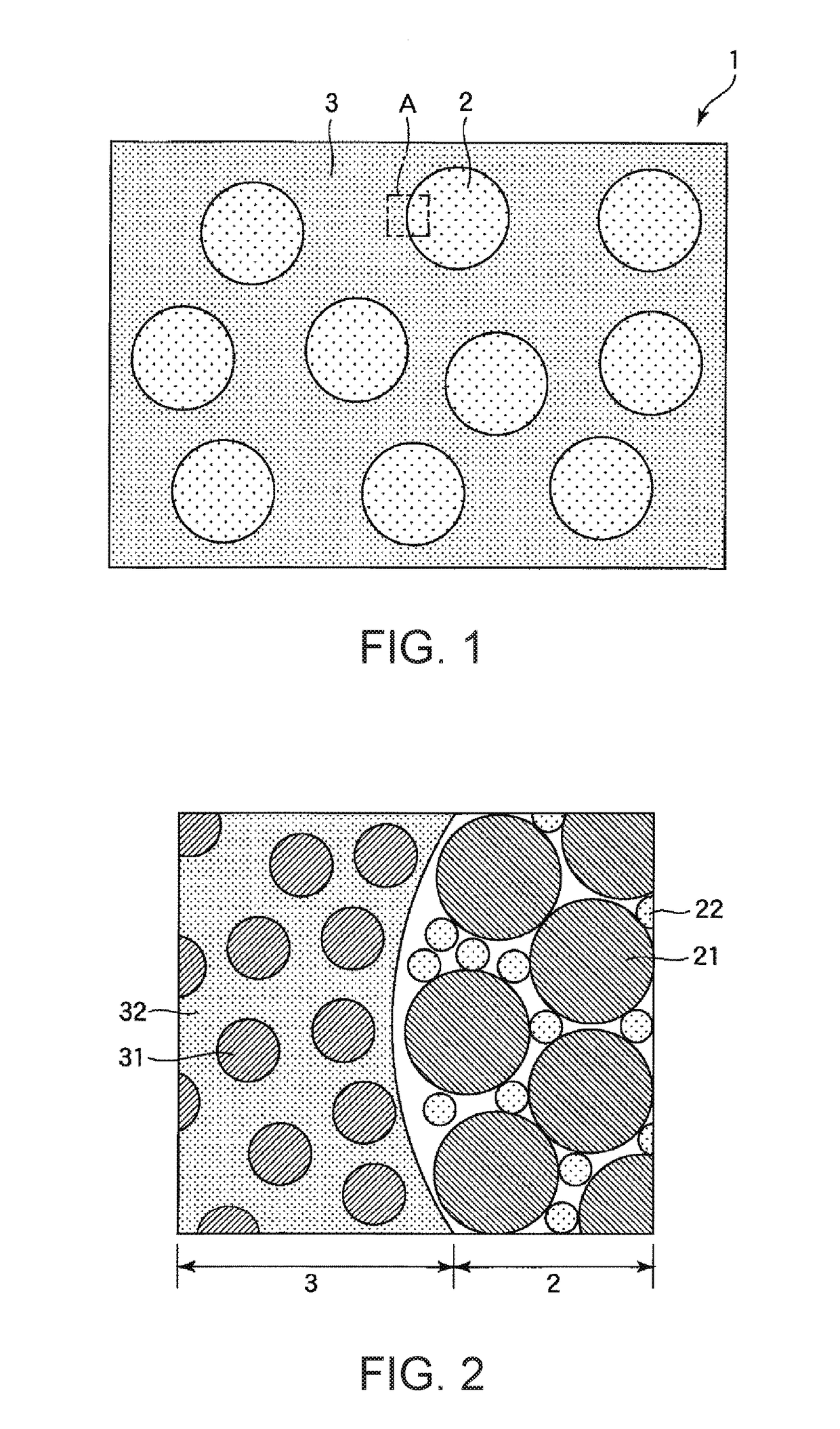
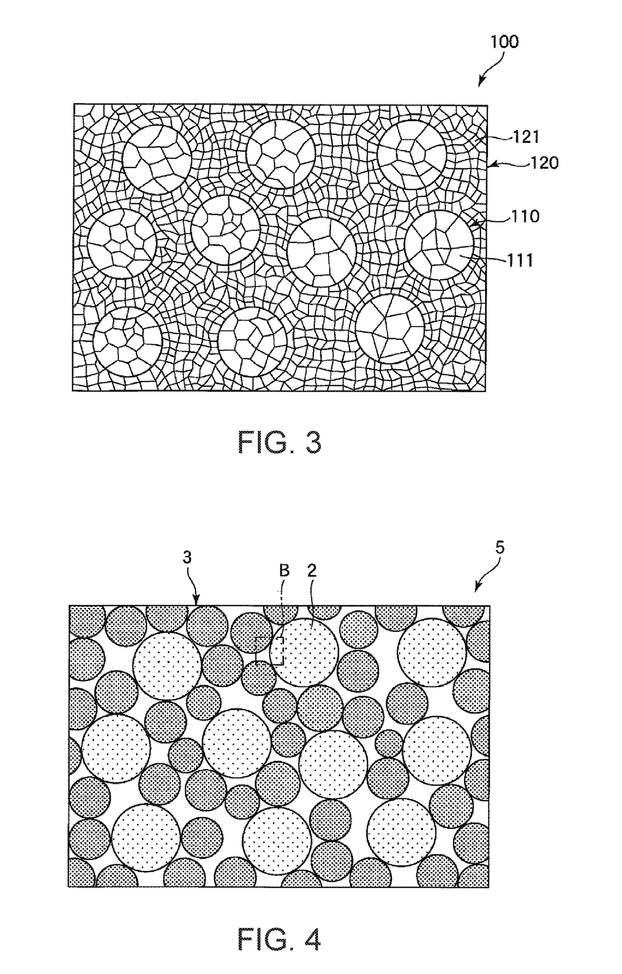
A compound for metal powder injection molding includes secondary particles in which first metal particles are bound to one another, and a matrix region including a binder and second metal particles composed of the same constituent material as the first metal particles and having a smaller average particle diameter than the first metal particles. The constituent material of the first metal particles is any of an Fe-based alloy, an Ni-based alloy, and a Co-based alloy.

Description

BACKGROUND1. Technical Field[0001]The present invention relates to a compound for metal powder injection molding, a metal powder molded body, a method for producing a sintered body, and a sintered body.2. Related Art[0002]One known method for molding a metal powder into a molded body is a compression molding method in which a granulated powder including a metal powder and an organic binder is filled in a given molding die and then compressed to obtain a molded body in a given shape. The obtained molded body is subjected to a degreasing treatment of removing the organic binder and a firing treatment of sintering the metal powder, thereby forming a metal sintered body. Such a technique is known as a powder metallurgy technique and is capable of producing a large amount of metal sintered bodies in complicated shapes matching the shapes of the molding dies, and therefore has recently been widely adopted in many industrial fields.[0003]For example, JP-A-2001-152205 discloses a metal powd...

Claims


Application Information

Patent Timeline
IPC IPC(8): B22F1/00B22F3/22B22F1/10B22F1/103B22F1/107B22F1/148
CPCB22F1/0059B22F1/0074B22F3/225B22F2301/35B22F2003/247B22F3/24B22F9/026B22F2001/0066B22F3/1007B22F2998/10B22F1/103B22F1/10B22F1/107B22F1/148B22F3/10B22F7/06B22F2301/00
Inventor NAKAMURA, HIDEFUMIHIDESHIMA, YASUTOSHI
Owner SEIKO EPSON CORP
Why Eureka
Try Eureka