Coated article having low-e coating with ir reflecting layer(s) and doped titanium oxide dielectric layer(s) and method of making same

a technology of ir reflecting layer and titanium oxide dielectric layer, which is applied in the direction of vacuum evaporation coating, coating, sputtering coating, etc., can solve the problems of thermal or lattice stress, thermal stability of materials, and typically not heat stable, and achieve high refractive index (n), and low e stack performance deterioration

Active Publication Date: 2018-09-06
GUARDIAN GLASS LLC
View PDF0 Cites 8 Cited by
  • Summary
  • Abstract
  • Description
  • Claims
  • Application Information

AI Technical Summary

Benefits of technology

[0003]Conventional low-E coatings are disclosed, for example and without limitation, in U.S. Pat. Nos. 6,576,349, 9,212,417, 9,297,197, 7,390,572, 7,153,579, and 9,403,345, the disclosures of which are hereby incorporated herein by reference.
[0004]Certain low-E coating utilize at least one transparent dielectric layer of titanium oxide (e.g., TiO2), which has a high refractive index (n), for antireflection and / or coloration purposes. See for example U.S. Pat. Nos. 9,212,417, 9,297,197, 7,390,572, 7,153,579, and 9,403,345. Although high refractive index dielectric materials such as TiO2 are known and used in low-E coatings, these materials are not thermally stable and are typically not heat stable after tempering process of about 650C. for 8 minutes, due to film crystallization (or change in crystallinity) in as-deposited or post-tempering state, which may in turn induce thermal or lattice stress on adjacent layers in the film stack. Such stress can further cause change in physical or material properties of the stack and hence impact on the Ag layer, which results in deteriorated low E stack performance. In other words, conventional TiO2 layers are typically sputter-deposited so as to realize a crystalline structure, which leads to damage to the stack upon HT as explained above.
[0005]Example embodiments of this invention solve these problems by providing a high index doped titanium oxide layer for use in low-E coatings that both has a high refractive index (n) and is substantially stable upon heat treatment (HT).

Problems solved by technology

Although high refractive index dielectric materials such as TiO2 are known and used in low-E coatings, these materials are not thermally stable and are typically not heat stable after tempering process of about 650C. for 8 minutes, due to film crystallization (or change in crystallinity) in as-deposited or post-tempering state, which may in turn induce thermal or lattice stress on adjacent layers in the film stack.
Such stress can further cause change in physical or material properties of the stack and hence impact on the Ag layer, which results in deteriorated low E stack performance.

Method used


Image

  • Coated article having low-e coating with ir reflecting layer(s) and doped titanium oxide dielectric layer(s) and method of making same
  • Coated article having low-e coating with ir reflecting layer(s) and doped titanium oxide dielectric layer(s) and method of making same
  • Coated article having low-e coating with ir reflecting layer(s) and doped titanium oxide dielectric layer(s) and method of making same

Examples


example 1

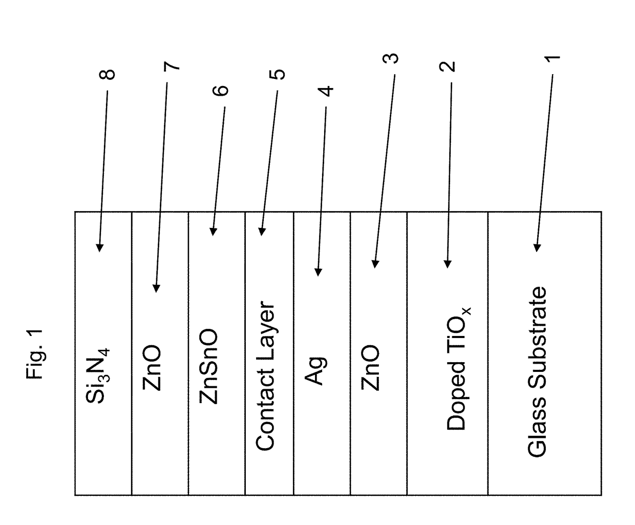
[0043]Example 1 was a low-E coating on a glass substrate according to the FIG. 1 embodiment, for comparing to FIG. 2 above. The Example 1 layer stack was glass / Ti SnOx(27 nm) / ZnO(4 nm) / Ag(11 nm) / NiTiNbOx(2.4 nm) / ZnSnO(10 nm) / ZnO(4 nm) / SiN(10 nm), where the ZnO layers were doped with Al. Example 1 was the same coating stack as the Comparative Example (CE) described above regarding FIG. 2, except that in Example 1 the TiO2 layer of the CE was replaced with Sn-doped titanium oxide (TiSnOx). The high index layer 2 was titanium oxide doped with tin (TiSnOx) in Example 1. The oxygen depleted atmosphere in which the TiSnOx layer 2 was sputter deposited contained 20% oxygen gas and 80% argon gas (4 sccm O2 and 16 sccm Ar). Power applied to the Ti target was 500 W, and power applied to the Sn target was 50 W. Metal content of the TiSnOx layer 2 was 88% Ti and 12% Sn (atomic %). The coating of Example 1 had a normal emissivity (En) of 0.068. The TiSnOx layer 2 of Example 1 had a refractive in...

example 2

[0045]Example 2 (FIG. 5) had the same layer stack as Example 1 (FIGS. 4 and 6) above, with the sole difference being that the TiSnOx layer 2 in Example 2 was sputter deposited in a gaseous atmosphere containing 70% oxygen gas whereas the TiSnOx layer 2 in Example 1 was sputter depositing in a gaseous atmosphere containing 20% oxygen gas. The high index layer 2 was titanium oxide doped with tin (TiSnOx) in both of Examples 1-2. The oxygen depleted atmosphere in which the TiSnOx layer 2 was sputter deposited in Example 1 contained 20% oxygen gas and 80% argon gas (4 sccm 02 and 16 sccm Ar), but in Example 2 the atmosphere was modified to contain 70% oxygen gas and 30% argon gas (14 sccm O2 and 6 sccm Ar). Power applied to the Ti and Sn targets, the HT, and the metal content of the layer 2, were all the same in Examples 1 and 2. It can be seen by comparing FIG. 5 (Example 2 with 70% oxygen gas in sputtering atmosphere) to FIG. 6 (Example 1 with 20% oxygen gas in sputtering atmosphere),...

example 3

[0046]Example 3 was a low-E coating on a glass substrate according to the FIG. 1 embodiment, for comparing to FIG. 2 above. The Example 3 layer stack was glass / TiYOx(27 nm) / ZnO(4 nm) / Ag(11 nm) / NiTiNbOx(2.4 nm) / ZnSnO(10 nm) / ZnO(4 nm) / SiN(10 nm), where the ZnO layers were doped with Al. Example 3 was the same coating stack as Example 1 and the Comparative Example (CE) described above regarding FIG. 2, except that in Example 3 the high index layer 2 was Y-doped titanium oxide (TiYOx). The high index layer 2 was titanium oxide doped with yttrium (TiYOx) in Example 3, and sputter deposited in an oxygen depleted atmosphere. Metal content of the TiYOx layer was 95% Ti and 5% Sn (atomic %). The composition ratio of the TiYOx was Y:Ti:O corresponding to 5:95:245 (atomic). The TiYOx layer 2 of Example 3 had a refractive index (n), at 550 nm, of 2.42. FIG. 9 shows the data of Example 3, before and after HT, and should be compared to the CE of FIG. 2. In FIGS. 2 and 9 at the right side where th...


PUM

PropertyMeasurementUnit
refractive indexaaaaaaaaaa

Abstract

A coated article includes a low emissivity (low-E) coating having at least one infrared (IR) reflecting layer of a material such as silver, gold, or the like, and at least one high refractive index layer of or including titanium oxide and at least one additional metal. A doped titanium oxide layer(s) is designed and deposited in a manner so as to be amorphous or substantially amorphous (as opposed to crystalline) in the low-E coating, so as to better withstand optional heat treatment (HT) such as thermal tempering and reduce haze. The high index layer may be a transparent dielectric high index layer in preferred embodiments, which may be provided for antireflection purposes and/or color adjustment purposes, in addition to having thermal stability.

Description

[0001]This application relates to a coated article including a low emissivity (low-E) coating having at least one infrared (IR) reflecting layer of a material such as silver, gold, or the like, and at least one high refractive index layer of or including doped titanium oxide (e.g., TiO2 doped with at least one additional element). The doped titanium oxide layer(s) is designed and deposited in a manner so as to be amorphous or substantially amorphous (as opposed to crystalline) in the low-E coating, so as to better withstand optional heat treatment (HT) such as thermal tempering. The high index layer may be a transparent dielectric high index layer in preferred embodiments, which may be provided for antireflection purposes and / or color adjustment purposes, in addition to having thermal stability. In certain example embodiments, the low-E coating may be used in applications such as monolithic or insulating glass (IG) window unit, vehicle windows, of the like.BACKGROUND AND SUMMARY OF ...

Claims


Application Information

Patent Timeline
Patent Type & Authority Applications(United States)
IPC IPC(8): C23C14/18C03C17/36C03C17/34
CPCC23C14/18C03C17/34C03C17/366C23C14/185C03C17/36C03C17/3618C03C17/3644C03C17/3681
Inventor ZHANG, GUIZHENSCHWEIGERT, DANIELDING, GUOWENLEE, DANIELCLAVERO, CESARJEWHURST, SCOTTSARAF, GAURAVLE, MINHMURPHY, NESTOR P.FRANK, MARCUS
Owner GUARDIAN GLASS LLC
Why Eureka
Try Eureka