
Apparatus for plasma confinement and for ion separation

a plasma confinement and apparatus technology, applied in the field of apparatus for plasma confinement and ion separation, can solve the problem that the toroidal chamber of the tokamak cannot escape the problem of plasma leakage, and achieve the effect of reducing co2 emissions into the atmosphere and being easy to produce in mass

Inactive Publication Date: 2018-09-06
MIZUKI MIKISO
View PDF2 Cites 2 Cited by
  • Summary
  • Abstract
  • Description
  • Claims
  • Application Information

AI Technical Summary

Benefits of technology

The design of the patent text is an apparatus for separating gases using plasmas. The apparatus uses strong magnets to create a confined space where the plasmas can move without losing their energy. This design prevents problems with traditional plasma designs and increases the chance of nuclear interactions. The apparatus is simple and efficient, with little electrical power needed to produce separated gases. This can help reduce carbon fuel consumption and the emissions of CO2 from power stations. Additionally, if the apparatus can produce hydrogen and oxygen gases without using large amounts of electricity, it can lead to a reduction in CO2 emissions and the reliance on coal for electric power generation.

Problems solved by technology

However, use of the toroidal chamber of Tokamak can never escape from the plasma leakage problem due to (i) the unequal spacing of the poloidal magnets, surrounding the torus surface cross section-wise, which have different size separation distances between inside and outside curved wall surfaces, and (ii) the induced forces pointed sideway outwards by the interactions between charged ions moving inside and the vertically oriented applied poloidal magnetic field lines.
Although various designs of Stellarator attempt to minimize the orbit migration problem, they have to deal with complex chamber designs which pose engineering problems with difficult implementations.

Method used


Image

  • Apparatus for plasma confinement and for ion separation
  • Apparatus for plasma confinement and for ion separation

Examples


Embodiment Construction

[0031]In the current designs of Tokamak and Stellarators, plasma streams are generated inside and accelerated to raise the orbiting speeds and temperatures of plasma lumps inside the respective confinement chambers. Plasmas in rapid motion through applied directional magnetic fields must face natural drifting path problems due to the unavoidable interaction between the plasma orbital motion and the applied poloidal magnetic fields.

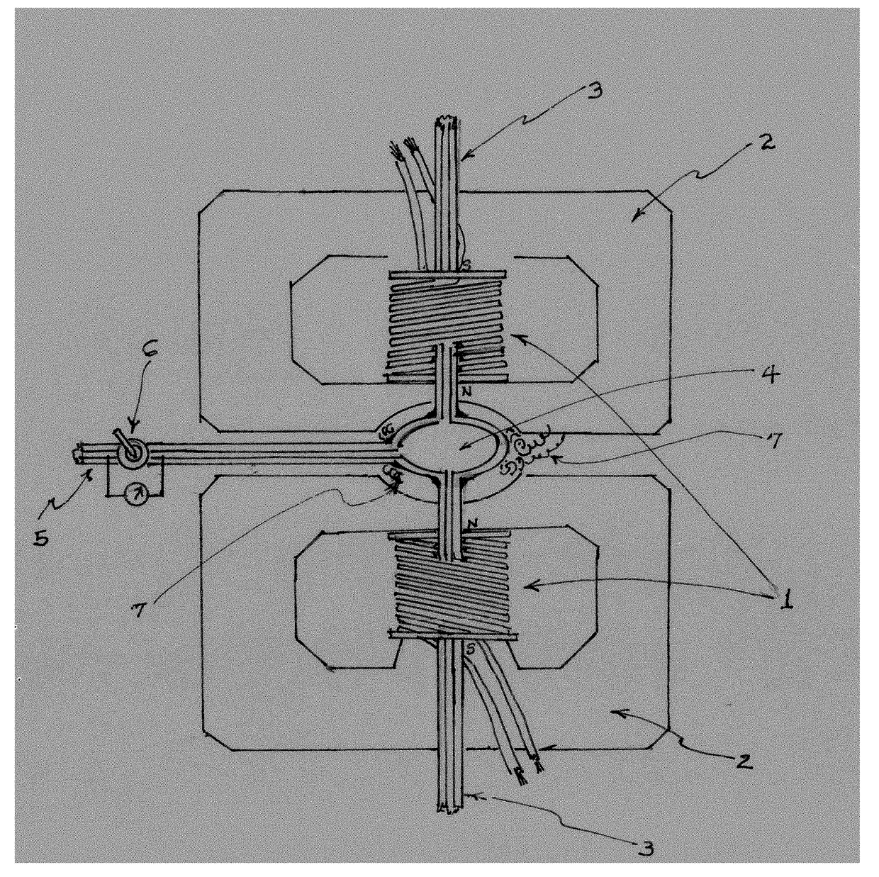
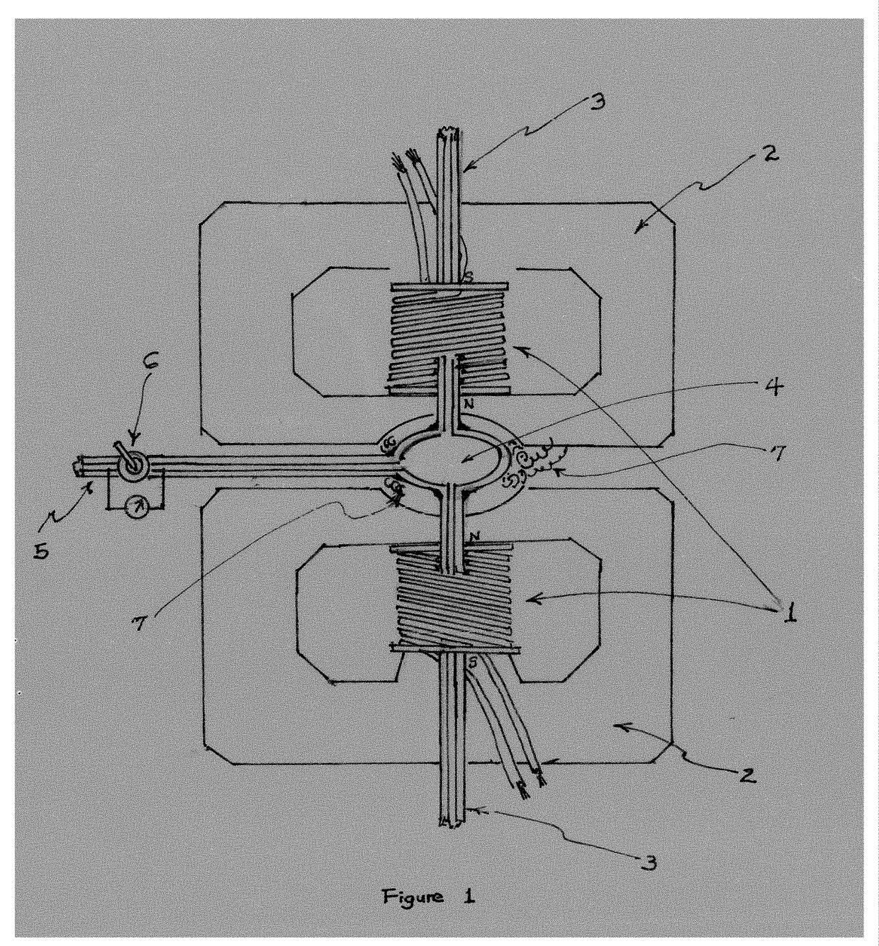
[0032]The invented apparatus confines plasma cloud at the center of a closed round chamber 4 in high density, and rapidly rotates the densely-packed plasmas to raise temperature through high rotation rates using circularly positioned solenoids 7, or circular arrays of permanent magnet in the place. This eliminates the path drift problems.

[0033]The apparatus design calls for the second purpose of separating positively and negatively charged ionized bodies. This mode of application provides an excellent means for yielding massive and inexpensive hydrogen fue...


PUM

PropertyMeasurementUnit
magnetic fieldaaaaaaaaaa
densityaaaaaaaaaa
temperatureaaaaaaaaaa

Abstract

Twin bar (electro)magnets with the North poles facing each other generate magnetic field lines converging into the middle, providing a space to place plasma cloud in magnetic confinement for thermonuclear fusion experiments. Source materials are injected through nozzles connected to axial pipes, and end products are taken out at the periphery of the reaction chamber. In ion separation, the source materials are injected at the periphery of the reaction chamber causing rapid rotation, and ions are attracted by electric potentials applied to the chamber walls. Naturally separated ions are expelled through the axial output pipes. The proposed apparatus for ion separation provides inexpensive means for producing massive volumes of hydrogen and oxygen gases. Use of hydrogen fuel can reduce consumption of carbon fuels, easing the global problem of rising temperature due to emission of CO2 gases.

Description

BACKGROUND OF INVENTIONField of Invention[0001]The physical natures of a black hole can best be characterized using an unpublished physical model of proprietary information. The model uses twin magnetic dipoles with two of the same North poles juxtaposed facing each other using usual terminology. Given a bar magnet with N / S poles, the magnetic field lines are defined here to run through the body of the magnet from N to S pole, go outside the body of the magnet, and return to the N pole, completing closed circuits of apple-shaped dipole magnetic field lines running in multiple layers.[0002]A sufficiently large black hole has such a magnetic dipole pair with properties of; (1) spiral converging movements of charged particles on the accretion disk due primarily to the gravitational pull right on the commonly shared plane of the dipole twins, (2) separation of charged particles on the accretion disc due to the handedness of charged particles in movement by inherent nature, and (3) gener...

Claims


Application Information

Patent Timeline
Patent Type & Authority Applications(United States)
IPC IPC(8): H01H1/10H01J49/00F02B43/12C10L3/00G21B1/05
CPCH01H1/10H01J49/0031C10L2290/40C10L3/00G21B1/05F02B43/12Y02E30/10
Inventor MIZUKI, MIKISO
Owner MIZUKI MIKISO
Learn More