Plant and process for ammonia production with cryogenic purification, and related method of revamping

a technology of ammonia production and plant and process, which is applied in the direction of liquefaction, lighting and heating apparatus, chemical production, etc., can solve the problems of increasing the consumption level of the compressor used, and the removal of inerts, so as to reduce the consumption and reduce the loss of pressure of the feed gas. , the effect of reducing the suction pressure of the synthesis gas compressor

Active Publication Date: 2018-09-20
CASALE SA
View PDF7 Cites 4 Cited by
  • Summary
  • Abstract
  • Description
  • Claims
  • Application Information

AI Technical Summary

Benefits of technology

[0016]The invention aims to overcome the abovementioned problems and limitations of the prior art. In greater detail, the invention aims to provide a process for the ammonia production comprising a cryogenic purification step which, compared to the prior art, allows: smaller pressure loss of the feed gas, higher suction pressure of the synthesis gas compressor and lower consumption thereof, greater efficiency of hydrogen recovery and inert gases removal, reduced circulation of the inerts in the synthesis loop, smaller excess air requirement.

Problems solved by technology

Said technology has a number of well-established advantages and is used in many ammonia plants around the world; however, it still has a number of drawbacks and hence margins for improvement.
This creates a drawback consisting in the loss of pressure of the feed gas.
Said loss in pressure increases the consumption level of the compressor used to raise the pressure of the gas purified in the synthesis loop.
Another limitation of the prior art is that the sole operational variable for controlling the cryogenic purification process is represented by the aforementioned expansion of the feed gas.
The removal of the inerts occurs accordingly, but is not directly controlled.
It follows that the prior art is not entirely effective as regards removal of the inerts.
The separation of argon, in particular, is problematic owing to the low concentration of the argon and its condensation temperature which is close to that of nitrogen.
Another disadvantage is given by the fact that a quantity of residual hydrogen, contained in the waste stream, is lost.
However, these methods require costly modifications of the air compressor in order to increase its flowrate.
Typically said air compressor is driven by a gas turbine, and in some cases it is also required to modify said turbine, resulting in further costs.
Alternatively it is possible to install a second air compressor in parallel with the existing compressor, but this solution is also costly and not very attractive since it requires a new machine and associated space for its installation.
Another problem of the revamping measures is that the apparatuses of the plant are made to operate at their maximum capacity and in these conditions it has been noted that the performance for the inerts separation gets worse with respect to the rated conditions.
This has negative consequences on the synthesis section, resulting, in some cases, in the need to install an additional reactor or revamp or replace the synthesis gas compressor.
In other words it has been noted that the cryogenic purification unit creates a considerable bottleneck in the plant.
A further drawback of the known method of revamping these plants is that a significant increase in the excess air generally requires adaptation of the apparatuses and / or introduces problems such as an increase in the pressure losses and / or increase in energy consumption.
As a result the above described methods of the prior art for revamping the ammonia plants are not entirely satisfactory and may be scarcely attractive from point of view of costs.

Method used


Image

  • Plant and process for ammonia production with cryogenic purification, and related method of revamping
  • Plant and process for ammonia production with cryogenic purification, and related method of revamping
  • Plant and process for ammonia production with cryogenic purification, and related method of revamping

Examples


Embodiment Construction

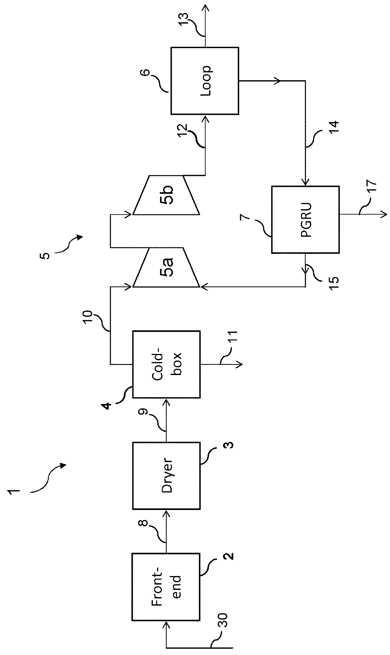
[0062]FIG. 1 shows a first embodiment of the invention in which a plant for ammonia synthesis, overall denoted by the reference number 1, comprises a front-end section 2 fed by a hydrocarbon source 30 (for example natural gas); a dryer 3; a cryogenic separation unit 4; a compression section 5; a synthesis loop 6; a hydrogen recovery unit 7.

[0063]The cryogenic unit 4 is also called “cold-box” in short. The unit 7 processes a purge stream 14 extracted from the synthesis loop 6 and for this reason is also called PGRU (Purge Gas Recovery Unit).

[0064]The front-end section 2 produces a synthesis gas 8 containing hydrogen and nitrogen in a molar ratio lower than 3, and preferably less than or equal to 2.5. In other words said synthesis gas 8 contains a certain excess of nitrogen due, for example, to excess air during a secondary reforming step. The gas 8 typically contains inert gases (mainly methane and argon) and water; moreover it may contain small quantities of ammonia.

[0065]The gas 8 ...


PUM

PropertyMeasurementUnit
molar ratioaaaaaaaaaa
temperatureaaaaaaaaaa
molar ratioaaaaaaaaaa

Abstract

Process for the synthesis of ammonia from a make-up gas containing hydrogen and nitrogen, said process comprising: generation of a synthesis gas (8) containing hydrogen and nitrogen in a molar ratio lower than 3, inside a front-end section (2); a first cryogenic purification, designed to remove nitrogen and raise said molar ratio; conversion of the synthesis gas into ammonia (13) inside a high-pressure synthesis loop (6), with extraction from said loop of a purge stream (14) containing hydrogen and inert gases; wherein at least a portion of said purge stream (14) undergoes a further purification in order to recover at least part of the hydrogen contained therein, obtaining at least one stream (15, 15a, 16, 18) containing recovered hydrogen which is recycled to the process.

Description

FIELD OF APPLICATION[0001]The invention relates to a plant and a process for the ammonia production comprising a stage for cryogenic purification of the synthesis gas. The invention also relates to a method for revamping ammonia plants with cryogenic purification.PRIOR ART[0002]The industrial production of ammonia involves the catalytic reaction of a synthesis gas (“make-up gas”) comprising hydrogen and nitrogen in a molar ratio of 3:1 inside a high-pressure synthesis loop operating usually at about 80-300 bar.[0003]The make-up gas is produced in a front-end section, upstream of the synthesis loop, by means of reforming of a hydrocarbon feedstock, for example natural gas.[0004]A known technique for the ammonia production, described for example in U.S. Pat. No. 3,442,613, comprises two-stage reforming, i.e. primary and secondary reforming, the secondary reforming being carried out with air in excess, and subsequent cryogenic purification of the synthesis gas. Said cryogenic purificat...

Claims


Application Information

Patent Timeline
Patent Type & Authority Applications(United States)
IPC IPC(8): F25J3/02C01C1/04
CPCF25J3/0276F25J3/0252C01C1/0476F25J2205/40F25J2205/60F25J2205/80F25J2210/02F25J2210/20F25J2215/02F25J2245/02C01B3/025C01B3/501C01B3/506C01B3/56C01B2203/046C01B2203/146C01B2203/043C01B2203/0405Y02P20/52F25J3/0219F25J3/0233F25J2210/04F25J2210/06F25J2230/32
Inventor FILIPPI, ERMANNOOSTUNI, RAFFAELE
Owner CASALE SA
Why Eureka
Try Eureka