

Nonhydrocarbon gas separation device and nonhydrocarbon gas separation method
a non-hydrocarbon gas and separation device technology, applied in the direction of separation processes, gaseous fuels, fuels, etc., can solve the problems of increasing the power to send non-hydrocarbon gas to the recovery facility, increasing the size of equipment and piping constructing the non-hydrocarbon gas separation device, and increasing the cost of facilities. , to achieve the effect of preventing the increase in the size of equipmen
Active Publication Date: 2018-09-27
JGC CORP
View PDF8 Cites 4 Cited by
- Summary
- Abstract
- Description
- Claims
- Application Information
AI Technical Summary
Benefits of technology
The present invention has a configuration where two separation modules are connected in series to separate non-hydrocarbon gas from natural gas. The pressure of the non-hydrocarbon gas in the first module is higher than the second module, which prevents an increase in equipment size while increasing the discharge pressure of the non-hydrocarbon gas.
Problems solved by technology
Meanwhile, when the natural gas containing a non-hydrocarbon gas in a large amount is to be treated, equipment and piping constructing the non-hydrocarbon gas separation device tend to be increased in size, and there is a problem of an increase in facility cost.
In the case of the natural gas containing a non-hydrocarbon gas in a large amount, there is another problem in that power to send the non-hydrocarbon gas to the recovery facility is increased.
However, in the patent literatures, there is no description of a technology for efficiently sending the non-hydrocarbon gas while preventing an increase in size of the non-hydrocarbon gas separation device of a separation membrane mode.
Method used
View moreImage
Smart ImageViewing Examples

Examples
example 1
[0108]The calculations were performed under the same conditions as in Reference Example except that the pressure in the space of the first separation module 2a on the secondary side was changed to 600 kPa.
example 2
[0109]The calculations were performed under the same conditions as in Reference Example except that the pressure in the space of the first separation module 2a on the secondary side was changed to 1,800 kPa.
Login to View More PUM
| Property | Measurement | Unit |
|---|---|---|
| pressure | aaaaa | aaaaa |
| pressure | aaaaa | aaaaa |
| pressure | aaaaa | aaaaa |
Abstract
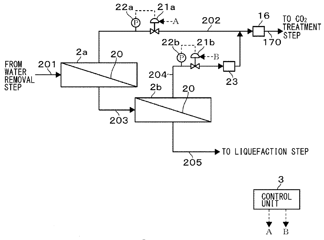
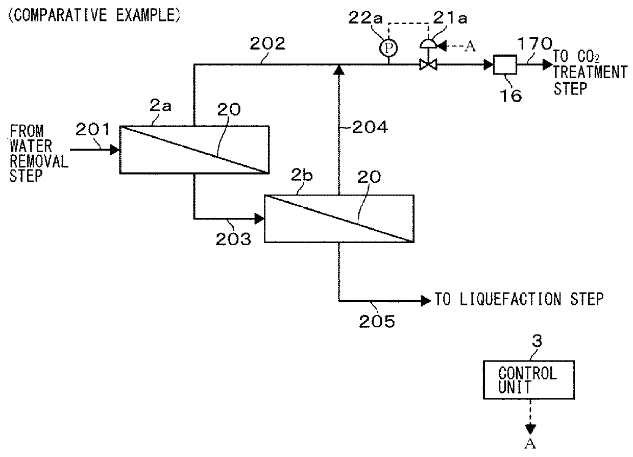
Provided are a non-hydrocarbon gas separation device and the like capable of increasing a discharge pressure of a non-hydrocarbon gas to a downstream side while preventing an increase in size of equipment. In the non-hydrocarbon gas separation device, a first separation module (2a) and a second separation module (2b) connected to each other in series are each configured to separate a non-hydrocarbon from a natural gas through use of a separation membrane (20). The non-hydrocarbon gas having been separated from the natural gas is discharged to each of discharge lines (202) and (204). At this time, a pressure of the first separation module (2a) on a discharge line (202) side is higher than a pressure of the second separation module (2b) on a discharge line (204) or (202) side.
Description
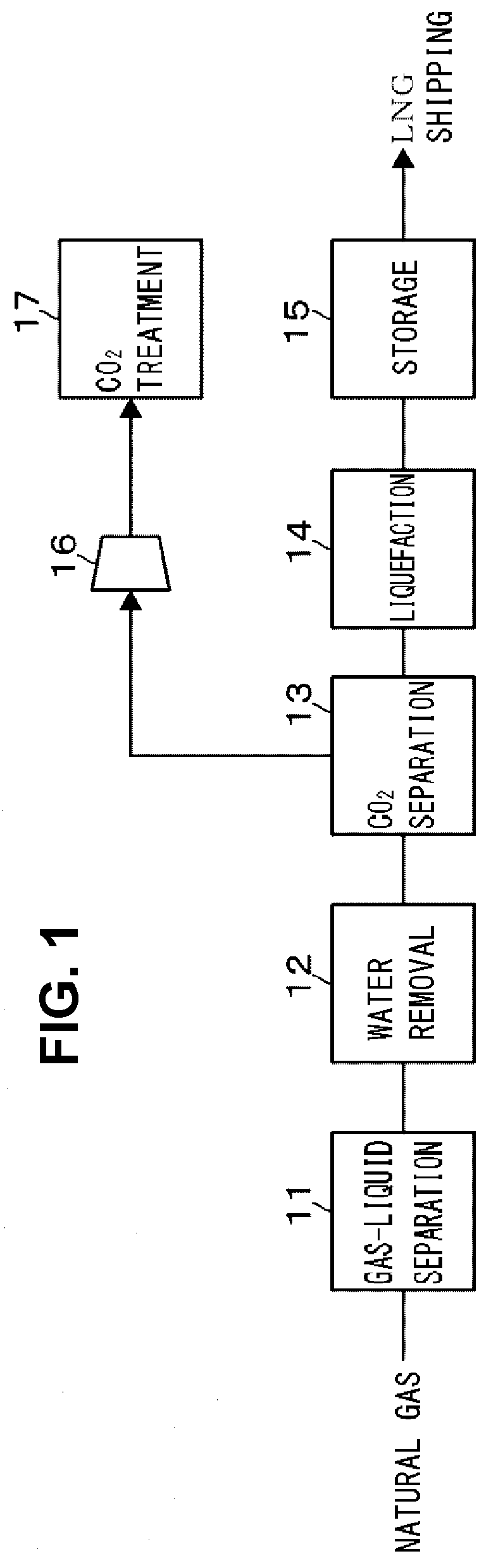
TECHNICAL FIELD[0001]The present invention relates to a technology for separating a non-hydrocarbon gas from a natural gas.BACKGROUND ART[0002]A natural gas produced from a wellhead is subjected to liquefaction pretreatment for separating impurities, and then cooled to be liquefied, and shipped as a liquidized natural gas (LNG).[0003]Some natural gases contain, as an impurity, a non-hydrocarbon gas, such as a carbon dioxide gas (CO2 gas) or a nitrogen gas (N2 gas), in a relatively large amount. When this kind of natural gas is treated, the non-hydrocarbon gas is discharged in a large amount in the liquefaction pretreatment.[0004]As a method of utilizing the non-hydrocarbon gas discharged in the liquefaction pretreatment of the natural gas and reducing the emission of the non-hydrocarbon gas into the atmosphere, there is given an example in which the non-hydrocarbon gas is utilized as an injection gas in enhanced oil recovery (EOR) or enhanced gas recovery (EGR) by being injected int...
Claims
Login to View More Application Information
Patent Timeline
 Patent Type & AuthorityApplications(United States)
IPC IPC(8): B01D53/22C10L3/10
CPCB01D53/226C10L3/105C10L3/104C10L2290/548C10L2290/60C10L2290/58C10L2290/46B01D2256/24B01D2256/245B01D2257/102B01D2257/504Y02C20/40
InventorHASEGAWA, HIROAKIUMINO, HIROSHIFUJIMURA, YASUSHIMATSUYAMA, AIKOOGURO, SYUICHINISHIDA, KEIICHITAKAHASHI, SHINJI
OwnerJGC CORP