Electromagnetic Tissue Ablation Device
- Summary
- Abstract
- Description
- Claims
- Application Information
AI Technical Summary
Benefits of technology
Problems solved by technology
Method used
Image
Examples
example a
RF and CRYO Device With Coaxial Extractable Needle and Shaft With Multi-polar Extractable Needles Made of a Memory-shape Alloy.
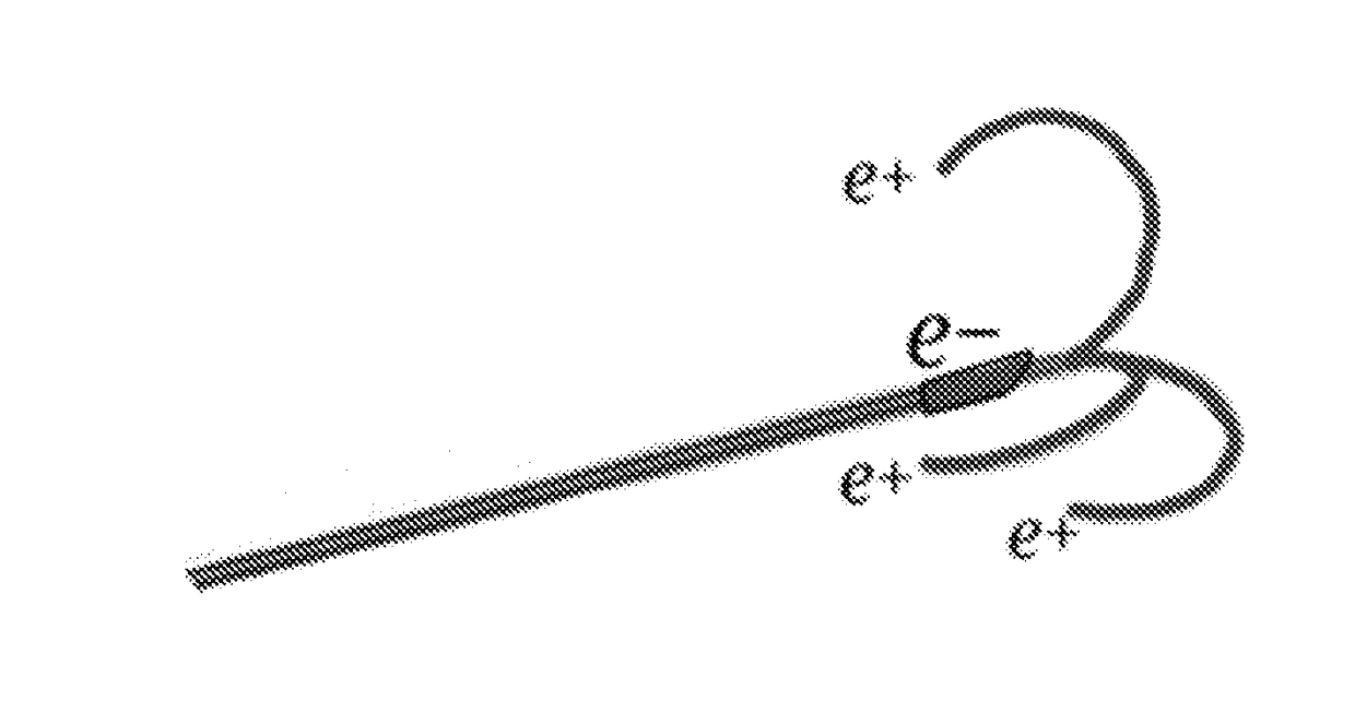
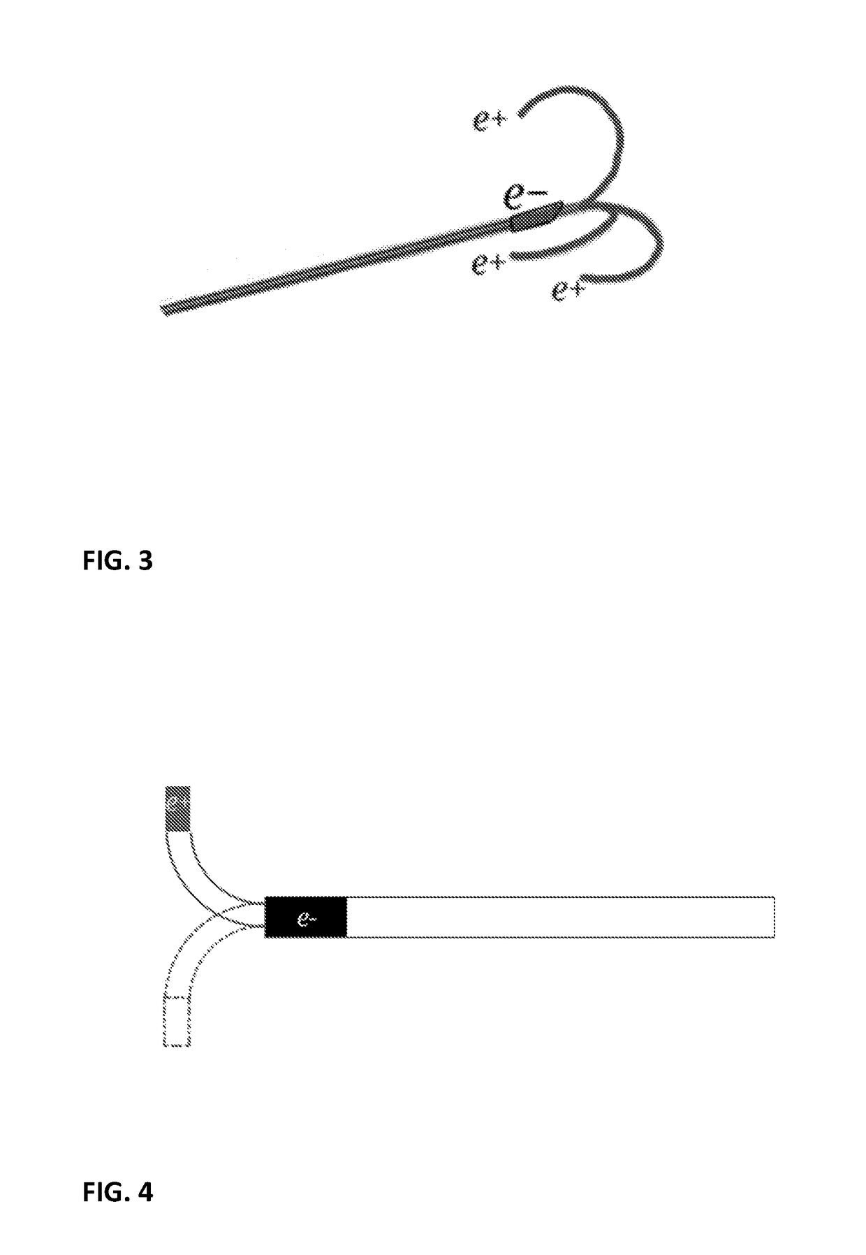
[0127]In this example the device provides multipolarity function between needles (>1). Needles are modified in shape after applying a telescopic action between body 7—body 8 (cathodes) and the rest of the active body (anodes).
[0128]These elements (cathodes and anodes) define the multi-polarity of the said system. The electricity stream goes from proximal to distal side of the active zone of the system.
[0129]Functioning System:
[0130]After the needle puncture on the desired area, the handle allows the reverse action of 7 and 8 in order to move the active needles 2 in the desired tissue area to be treated, taking advantage of the shape memory alloy (NiTinol) of the said needles 2.
[0131]A single electrical cable connects the energy generator with the needle 7 through the handle activating the cathode part of the system. Anode function can be activated by many ge...
example b
RF and CRYO Needle With Coaxial Extractable Needle and Multi-electrode Shaft
[0136]The device according to this example is designed with a multipolar function between the anodes, placed on 12 (12a, 12b, 12c) connected with electric cables 24 (24a, 24b, 24c) in radial position inside a shaft 23 and the cathode 18. The anode cables 24 are connected, through the handle, with the energy source generator.
[0137]Functioning System:
[0138]After the needle punctured and penetrated the area to ablate, acting on the handle the shaft 23 is retracted for the desired length in order to expose the cathode portion necessary to cover the volume of tissue to be treated.
[0139]The generator provides electrical distribution through the handle with a cable connected to 18 to activate the cathode function of the device. The anodic connections 24 are provided in the same way by cables connected to the generator. The handle carries on the control of the number of connected anodes and their charge. Multiple co...
example c
[0145]RF and CRYO Coaxial Extractable Catheter with Multi-electrode Shaft Implantable Using an Introducer Needle
[0146]The system provides multi-polar anode electrodes 25 in the proximal part of the catheter, realized inside a polymeric multi-lumen shaft 35.
[0147]A number of anode cables 34 (34a, 34b, 34c) provide connections of the proximal anode electrodes, positioned in the proximal side of the device, through the handle, with the RF generator.
[0148]Similarly, to the device of example B, the electricity stream goes from the anode proximal electrodes to the cathode electrode placed in the distal tip of the catheter device.
[0149]Functioning System:
[0150]After puncturing the patient's parenchimal tissue area with a metallic introducer needle, the telescopic catheter is introduced inside it.
[0151]Once the telescopic catheter is positioned inside the introducer needle it is possible to retrieve the introducer needle without moving the telescopic catheter.
[0152]An appropriate mechanism ...
PUM
 Abstract
Description
Claims
Application Information
 - R&D
- Intellectual Property
- Life Sciences
- Materials
- Tech Scout
- Unparalleled Data Quality
- Higher Quality Content
- 60% Fewer Hallucinations
Browse by: Latest US Patents, China's latest patents, Technical Efficacy Thesaurus, Application Domain, Technology Topic, Popular Technical Reports.
© 2025 PatSnap. All rights reserved.Legal|Privacy policy|Modern Slavery Act Transparency Statement|Sitemap|About US| Contact US: help@patsnap.com


