Methods and devices for evaluating the contents of materials

a technology of materials and contents, applied in the direction of fluid-tightness measurement, instruments, borehole/well accessories, etc., can solve the problems of limited resistivity, difficult and easy detection of petroleum and natural gas deposits

Active Publication Date: 2018-10-25
SMITH MICHAEL
View PDF14 Cites 6 Cited by
  • Summary
  • Abstract
  • Description
  • Claims
  • Application Information

AI Technical Summary

Benefits of technology

[0097]Centrifuging also or alternatively can sometimes be an aid to volatile extraction. Centrifuging an upright sample prior to volatile extraction, for example, can cause the vertical stratification of volatiles in the container, gases would migrate to the top, and oil would in general form a layer on top of water. This can be particularly useful in the analyses of volatiles in drilling muds from oil and gas exploration and production wells. Centrifuging following crushing can sometimes also have similar advantageous effects.
[0098]After all preparatory processes, if any, are complete the volatiles typically are extracted from the sample by reducing pressure on the sample by exposing the sample container to an inlet system that is under static vacuum and is not being actively pumped. The inlet system typically is sealed off to vacuum pumps at this point in the process, having been previously evacuated by vacuum pumps. Pressure is reduced on the sample by opening a valve between the sample container and the inlet system allowing gas to pass from the sample through the needle or other flow channel device into the inlet system. During a multi-stage extraction, at increasing levels of vacuum for each extraction, the first extraction results in a resulting pressure on the sample and in the inlet system that is determined by the gas pressure in the sample and the sample container, the void volume in the sample container, and the volume of the static inlet system. Each collection of extracted gas(ses) obtained by such a method is referred to as an “aliquot” herein. Thus, for example, the first extraction of a gas at atmospheric pressure or a different pressure may be referred to as Aliquot 1, with subsequent aliquot numbers each increasing by one, so that a three stage analyses will have Aliquot 1, Aliquot 2, and Aliquot 3. In typical practice, Aliquot 1 is extracted at a pressure of about 50 millibars. A typical Aliquot 2 is extracted at an initial pressure of about 5 millibars, and this pressure for a typical Aliquot 2 is decreased by a period of active pumping following initial trapping of the more volatile gases to about 0.001 millibars or less (e.g., as low as 0.0001 millibars or lower, or any range between about 0.001 millibars and 0.0001 millibars, such as 0.005-0.0005, 0.00075-0.00025, or 0.0009-0.0002 millibars). The step of causing this significant type of pressure drop in the system, device, or method of the invention is advantageous in methods in which a mass spectrometry analysis is performed on the samples, as mass spectrometry conditions typically require lower pressures than those in which aliquot extraction methods are performed in order to appropriately operate. Such pressure conditions will be known in the art (or provided by the mass spectrometry manufacturer) and the achievement of such levels of pressure can be achieved through any suitable means, with many such methods and devices being available.
[0099]As mentioned elsewhere, the methods of the invention can, in certain instances, include one or more steps in which potentially interfering gasses are removed from the released gas or the environment in which the gas is released. For example, in one aspect the invention can include the step of flooding the device in which the method is performed with an inert gas such as argon, so as to remove gasses from the device, which might provide false signals or results. Normal atmospheric gasses such as oxygen, nitrogen, and / or both, for example, can be substantially removed, or nearly completely removed, or even entirely removed (to detectable levels) by administering (“flooding”) to the device or a portion of the device in which the method is carried out with such an inert gas. Such a method also can be used as a method for refreshing the device between samples. Where an inert gas is used in such aspects, the inert gas can be any suitable gas that does not chemically react with the sample and does not cause any interferences with the chemical analyses of the samples' volatiles. In other aspects, a non-gaseous material, such as a liquid can be similarly used. The atmospheric or other interfering gas can be purged from the device, component, or environment in which the sample is being analyzed by, e.g., rapid vacuum extraction (e.g., applying a vacuum that is sufficiently strong to substantially or nearly entirely remove the purging inert gas for a duration of about 1 second or less). In another aspect, the method can comprise flowing an inert gas through the sample container or area to displace the potentially interfering gas. Such methods are not included in every application of the inventive methods. For example, where the method is performed on samples sealed at a collection site, such as a well site, such a step is typically not performed. However, such purging steps can be useful for analyzing the presence of target substances where such substances are or are suspected to be present only in very small amounts, such as with respect to methane and / or helium in samples that are associated with petroleum production or exploration sites.
[0100]Materials or methods also or alternatively can be used for removing other potentially interfering substances such as water vapor, for example, which is relevant to certain aspects of the invention in which water is formed and analyzed as a method for analyzing hydrocarbon content in samples. In one aspect, the invention is performed in the presence of a material that can capture essentially all, substantially all, or a relevant portion of the water vapor present around the sample that might be captured by either the trap or other tools for capturing substances used in the analytical method. For example, the system that is used for performing the method can comprise passages between system elements that are made of stainless steel, which promotes the absorption of water and thus removes water vapor contained in the gas content flowing through the system from reaching the next stage of the system.
[0101]The amount of volatile substances released from the sample, trapped on the trap, or analyzed by the analytical method of the inventive methods described herein can constitute any suitable proportion of the volatiles present in the sample, and the amount contained at each such stage in each of the aliquots obtained in multi-aliquot methods of the invention also can be any suitable amounts. Typically, most of the volatiles are captured by the method, such that at least about 90%, at least about 95%, at least about 97%, at least about 99% of the volatiles (excluding water, and particularly with respect to C1-C10 hydrocarbons and similarly structured organic compounds) are extracted from the sample, by the practice of the methods of the invention. The efficiency of the system typically also is high with respect to trapping of gasses that are condensable on the trap. Typically, condensable gasses that can be captured by the trap are not retained in the system in detectable levels. However, as discussed elsewhere herein certain gasses will not condense on the trap or otherwise be trapped by the trap and must be subject to handling by other means to be captured and analyzed by the method.
[0102]To exemplify (and clarify), methods of the invention can comprise analysis of a single aliquot, for example a single aliquot obtained under gentle / low vacuum conditions, or in other aspects the method can comprise obtaining and analyzing a plurality of aliquots from one or more samples and / or that are obtained under different conditions. For example, one method comprises obtaining two aliquots per sample, wherein the first aliquot is obtained by application of about 50 millibars (e.g., 10-100 millibars, such as 15-95 millibars, 20-90 millibars, 30-80 millibars, or 40-70 millibars) for about 3 minutes (e.g., 1-10 minutes, such as 1.5-8 minutes, 2-7.5 minutes, 2.5-5 minutes, or the like, in some cases it may be advantageous to perform the first aliquot extraction for shorter times in this or other contexts, such as 0.25-4 minutes, 0.33-3.5 minutes, 0.5-3 minutes, 0.5-4 minutes, 0.5-5 minutes, 0.5-2.5 minutes, 0.5-2 minutes, 0.75-3 minutes, 0.75-2.5 minutes, 0.75-2 minutes, or another similar time interval) and a obtaining a second aliquot by putting the sample under pressure conditions of about 5 millibars (e.g., about 1-10 millibars, about 2-8 millibars, about 3-7 millibars, or the like) for a period of about 10 minutes (such as 5-15 minutes, e.g., 6-12 minutes, 6-10 minutes, 5-9 minutes, 6-9 minutes, 7-9 minutes, 7-10 minutes, or about 7 minutes, about 8 minutes, or about 9 minutes), with the method optionally including a step of crushing / squeezing the sample during one or both aliquots, such as crushing the sample at the start of the first aliquot extraction, as described elsewhere herein. In some aspects, shorter extraction times (e.g., less than about 5 minutes, less than about 4.5 minutes, less than about 4 minutes, less than about 3 minutes, less than about 2.5 minutes, less than about 2 minutes, less than about 1.5 minutes, less than about 1 minute, or even shorter periods. In such aspects the parameters of the system and the method can be adjusted to facilitate shorter extraction time, such as, for example, using a relatively larger diameter needle system for the passage of volatiles out of a punctured sample container (e.g., use of a needle of about ⅛th or about 1 / 16th of an inch internal diameter as compared to about a 32nd of an inch diameter needle). In another approach, extraction time and / or purging time of the system can be reduced by to passing a non-condensable purge gas through the sample.

Problems solved by technology

While a significant advance, resistivity has proven to be of limited utility, especially in modern times in which easy to find petroleum and natural gas deposits are increasingly more difficult to detect with such technology.
However, fluid inclusion analysis also is of limited utility due to a number of issues, such as the content of the inclusion often not matching the present-day fluids in the geologic formation.

Method used


Image

  • Methods and devices for evaluating the contents of materials
  • Methods and devices for evaluating the contents of materials
  • Methods and devices for evaluating the contents of materials

Examples


example 1

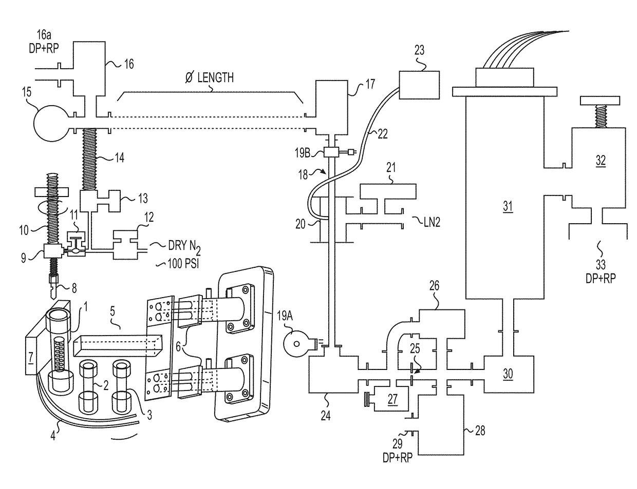
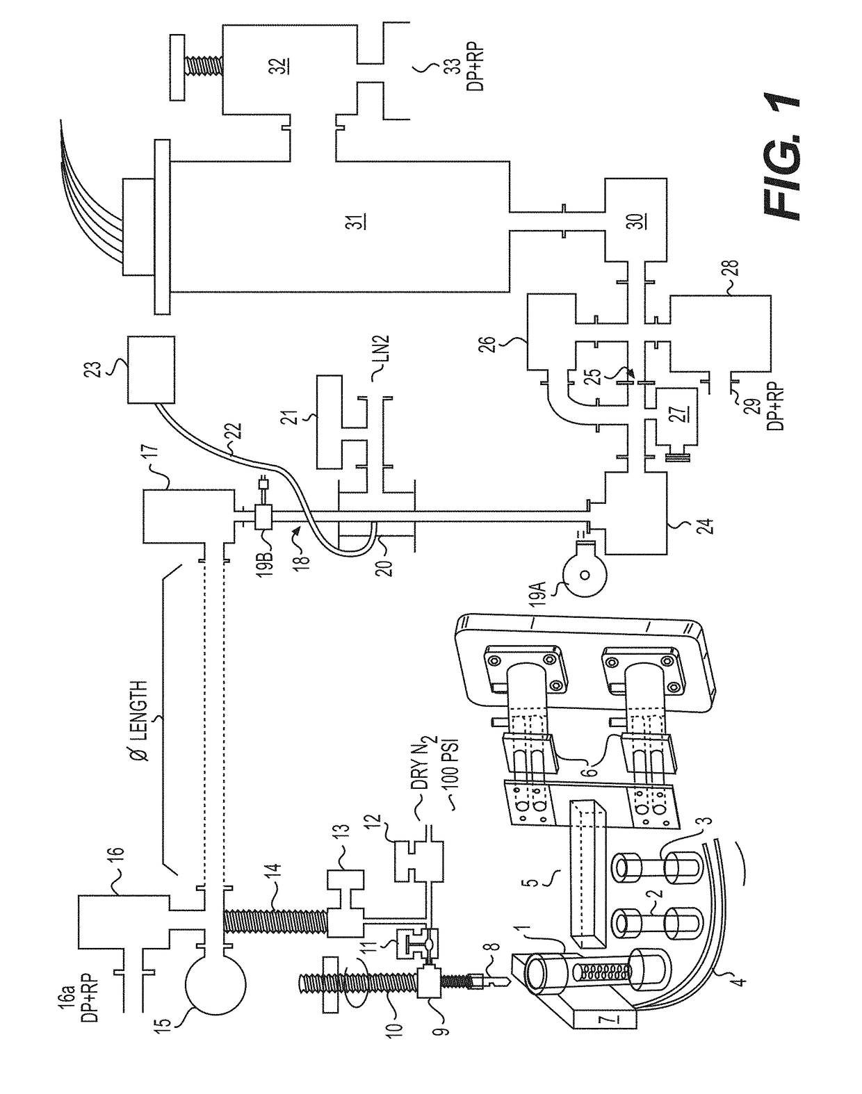
[0196]This example provides a description of an exemplary device / system according to certain aspects of the invention and that also is suitable for application of several of the inventive methods described herein. An overview of the exemplary device is provided in the following figure (FIG. 1).

[0197]With respect to the device / system shown above, #1 depicts a first sample container, as described elsewhere herein. The first sample container #1 contains the sample of the material, such as cuttings taken from an oil well. The sample container #1 in the case of the depicted system is sealed and made of an impermeable material. The top portion of any sample container used in the system, such as the first sample container #1, is penetrable by the needle #2, which provides a passageway and means for transferring gasses released from the sample into the rest of the system, either immediately after penetration and / or after generation through the application of one or more forces acting upon t...

example 2

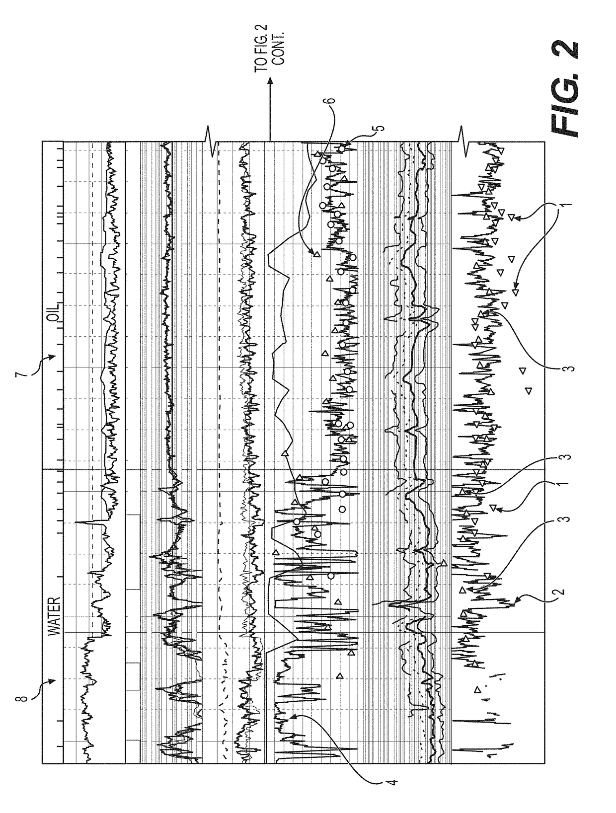
[0208]This example demonstrates the use of methods of the invention to determine oil and water saturation in a formation based on analysis of cuttings taken from an oil well, as well as permeability analysis obtained by analyzing a series of cuttings taken from the well.

[0209]Thirty samples of non-sealed cuttings taken from different depths in an oil well that had been stored in unsealed containers for a period of approximately three months under warehouse conditions in the summer (about 100-130 degrees F. estimated maximum daily temperature) were subjected to analysis using a device as described in Example 1 to provide information concerning the permeability of samples taken from different depths in the oil well, based on the release of target substances. The cuttings were subject to two runs of the system, forming two aliquots, based on the application of pressure conditions of 50 millibars and 5 millibars, respectively.

[0210]The right-hand column of FIG. 2, shown below, depicts a...

example 3

[0215]This example demonstrates the identification of an oil pay zone, through application of the inventive method on oil well cuttings, which were taken from a section of an oil well that was not being prospected based on application of pre-existing analytical methods.

[0216]Five hundred and eighteen cuttings taken from an oil well site, sealed at the well, were used in this analysis. Three aliquots were obtained from each cutting, using pressure conditions similar to those described in Example 2, plus an aliquot following intense sample dehydration. Permeability measures were obtained by the difference between aliquots 2 and aliquot 1 for each cuttings sample, #1. The data from the analysis were plotted and the actual plot of this data is shown in FIG. 3.

[0217]Numerous additional data points were also obtained and are reflected in FIG. 3, such as formic acid #2, acetic acid #3, oil saturated water #4, presence of C5-C10 paraffins #5, C6-C10 naphthenes #6, C6-C8 aromatics #7, and to...


PUM

PropertyMeasurementUnit
pressureaaaaaaaaaa
pressureaaaaaaaaaa
pressureaaaaaaaaaa

Abstract

Methods for determining the hardness and / or ductility of a material by compression of the material are provided as a first aspect of the invention. Typically, compression is performed on multiple sides of a geologic material sample in a contemporaneous manner. Devices and systems for performing such methods also are provided. These methods, devices, and systems can be combined with additional methods, devices, and systems of the invention that provide for the analysis of compounds contained in such samples, which can indicate the presence of valuable materials, such as petroleum-associated hydrocarbons. Alternatively, these additional methods, devices, and systems can also stand independently of the methods, devices, and systems for analyzing ductility and / or hardness of materials.

Description

CROSS-REFERENCE TO RELATED APPLICATIONS[0001]This application is a continuation of PCT / US2017 / 065921, filed Dec. 12, 2017 entitled Methods and Devices for Evaluation the Contents of Materials which claims the benefit of U.S. Provisional Application No. 62 / 434,399, filed Dec. 14, 2016, entitled Methods and Devices for Evaluating the Contents of Materials, the entirety of each of which being hereby incorporated by reference.FIELD OF THE INVENTION[0002]This invention pertains to novel methods of evaluating the contents of materials, including, for example, volatile substances such as petroleum-related hydrocarbons in geological materials, as well as devices that can be used in the practice of the methods and other applications.BACKGROUND OF THE INVENTION[0003]Human evaluation of the content of materials has probably been practiced for longer than any written records. However, the ability to use information associated with a material to understand the properties of associated materials,...

Claims


Application Information

Patent Timeline
Patent Type & Authority Applications(United States)
IPC IPC(8): E21B49/00E21B49/02G01N1/24G01N3/12G01N3/40
CPCE21B49/005E21B49/02G01N1/24G01N3/12G01N3/40H01J49/0422E21B43/26H01J49/00G01N3/08G01N33/241G01N2001/4033G01N1/4022G01N1/286G01N33/6848G01M3/202G01N2015/1043B29B17/0408B27K5/0005E21B49/08H01J49/0409H01J49/0468H01J49/26
Inventor SMITH, MICHAEL
Owner SMITH MICHAEL
Why Eureka
Try Eureka