Motor with separated permanent magnet torque and reluctance torque and its optimal efficiency control

a technology of which is applied in the direction of dynamo-electric converter control, dynamo-electric gear control, and magnetic circuit shape/form/construction, etc. it can solve the problems of inability to use in a wide speed range, inability to control permanent magnet torque and reluctance torque independently, etc., to reduce the processing difficulty of the motor, increase the reluctance torque, and increase the effect of permanent magnetic torqu

Active Publication Date: 2018-11-08
JIANGSU UNIV
View PDF16 Cites 24 Cited by
  • Summary
  • Abstract
  • Description
  • Claims
  • Application Information

AI Technical Summary

Benefits of technology

[0029]1) The proposed motor includes 3 stators and 1 rotor (composed of 2 axial rotors and 1 radial rotor). Each stator and rotor of the invention can be processed independently and installed modularly, thereby this can reduce the processing difficulty of the motor.
[0030]2) The distributed winding is adopted in radial stator, and the axial stator use concentrated winding. The use of distributed winding and radial reluctance rotor structure is conductive to the generation of greater reluctance torque. The use of concentrated winding and the surface mounted permanent magnet structure can produce higher permanent magnetic torque. The axial magnetic circuit generates the permanent magnetic torque, and the radial magnetic circuit generates the reluctance torque. By using the decoupling of axial and radial magnetic circuits, the separation and the independent control of the permanent magnetic torque and the reluctance torque are realized.
[0031]3) The use of multi-layer air slot structure in radial rotor is beneficial to increase the reluctance torque. The surface mounted permanent magnet (the surface sticking coefficient of permanent magnet is between 0.8-1) on the axial rotor is beneficial to the improvement of permanent magnet torque. The independent optimization of permanent magnet torque and reluctance torque is helpful to break through the torque density of conventional motors.
[0032]4) The radiuses of the 2 axial rotors are equal, and the radius of the radial rotor is different from the 2 axial rotors. The radius ratio of the left axial and the radial rotor is between 0.7-0.9, which is to ensure the maximum permanent magnet torque output ability, also greatly suppress the end leakage flux.
[0033]5) Under the condition that the radial radius of radial and axial rotor is fixed, the changing of the axial thickness ratio of radial and axial rotor (the ratio of the axial thickness of the radial rotor to the left axial rotor or the right axial rotor should be set at 0.2-0.8) can quickly adjust the proportion of the reluctance torque and permanent magnet torque.
[0034]6) The optimal efficiency control is divided into three regions, which can make the motor obtain / possess the high efficiency characteristic of the surface mounted permanent magnet motor at low speed, the high efficiency characteristic of the interior permanent magnet motor in medium high speed area, the high efficiency characteristic of synchronous reluctance motor at high speed area. It also can reduce the loss of permanent magnet eddy current, and maximize the utilization ratio of the reluctance torque produced by the radial stator and rotor and the permanent magnet torque produced by the axial motor respectively, furthermore achieve optimal efficiency control in different region.DESCRIPTION OF FIGURES

Problems solved by technology

However, the output torque of the permanent magnet motor is composed of permanent magnet torque and reluctance torque, and they are output at the same time, so the permanent magnet torque and reluctance torque cannot be controlled independently.
However, this scheme does not separate the radial and axial magnetic field and does not take into account the reluctance torque of the motor, so it cannot be used in wide speed range.

Method used


Image

  • Motor with separated permanent magnet torque and reluctance torque and its optimal efficiency control
  • Motor with separated permanent magnet torque and reluctance torque and its optimal efficiency control
  • Motor with separated permanent magnet torque and reluctance torque and its optimal efficiency control

Examples


specific example 1

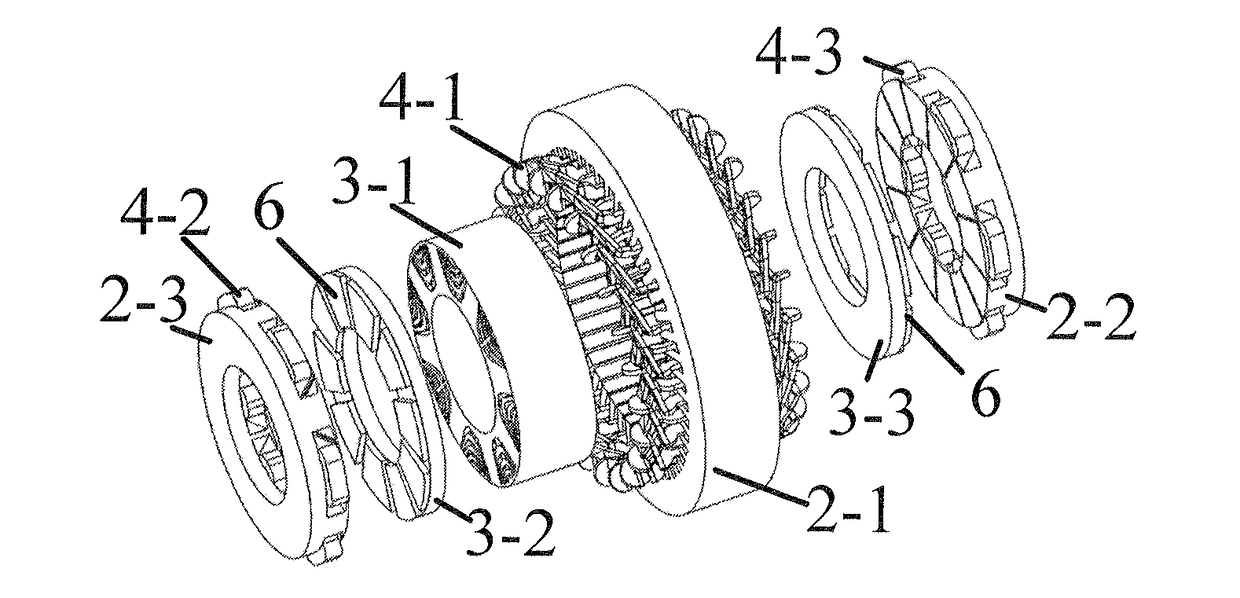
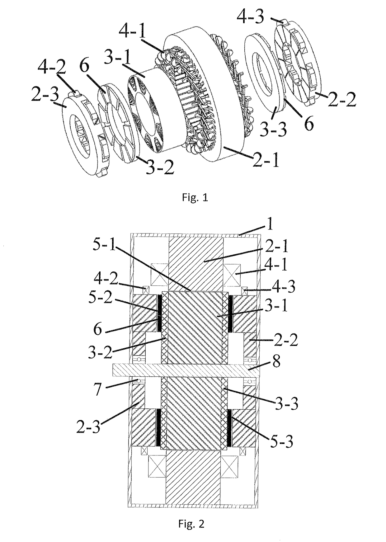
[0053]As shown in FIG. 1, the invention is a motor with separated permanent magnet torque and reluctance torque. The motor includes 3 stators and 3 rotors, 3 stators are: radial stator 2-1, right axial stator 2-2, left axial stator 2-3; the 3 rotors are: radial rotor 3-1, left axial rotor 3-2, and right axial rotor 3-3. The radial stator use the integer slot distributed winding 4-1, the left axial stator 2-3 use the fractional slot concentrated winding 4-2, and the right axial stator 2-2 use the fractional slot concentrated winding 4-3. The permanent magnets 6 are surface mounted on the left axial rotor 3-2 and the right axial rotor 3-3.

[0054]The radial motor uses inner rotor structure in this example. The inner ring of radial rotor 3-1 is a shaft 8. The inner ring of radial stator 2-1 is the radial rotor 3-1, and there is a radial air gap 5-1 between them. The two sides of the end of radial rotor 3-1 are connected with a left axial rotor 3-2 and a right axial rotor 3-3, respectivel...

specific example 2

[0062]As shown in FIG. 8, the invention is a motor with separated permanent magnet torque and reluctance torque. The motor includes 3 stators and 3 rotors, the 3 stators are: radial stator 2-1, right axial stator 2-2, left axial stator 2-3; the 3 rotors are: radial rotor 3-1, left axial rotor 3-2, and right axial rotor 3-3.

[0063]The radial motor of this specific example is an outer rotor structure, and the radial rotor 3-1 can be directly installed in the wheel to form a hub structure. The inner ring of radial stator 2-1 is the radial rotor 3-1, and there is a radial air gap 5-1 between them. The two sides of the end of the radial rotor 3-1 are set with a left axial rotor 3-2 and a right axial rotor 3-3 respectively. The left axial stator 2-3 and the right axial stator 2-2 are arranged on the outermost layer of the left axial rotor 3-2 and the right axial rotor 3-3 respectively. The pennanent magnets on the left axial rotor 3-2 and the right axial rotor 3-3 are arranged on the side ...

specific example 3

[0066]As shown in FIG. 9, the invention is a motor with separated permanent magnet torque and reluctance torque. The motor includes 3 stators and 3 rotors, 3 stators are: radial stator 2-1, right axial stator 2-2, left axial stator 2-3; the 3 rotors are: radial rotor 3-1, left axial rotor 3-2, and right axial rotor 3-3.

[0067]The motor of this specific example is inner rotor structure. The inner ring of radial rotor 3-1 is a shaft 8, the inner ring of radial stator 2-1 is the radial rotor 3-1, and there is a radial air gap 5-1. The left axial stator 2-3 and the right axial stator 2-2 are arranged side by side along the axial direction, meanwhile, the radial stator 2-1 is nested along the axial direction at the inner axis of the left axial stator 2-3 and the right axial stator 2-2. The left axial rotor 3-2 and the right axial rotor 3-3 are arranged on the outermost layer of the left axial stator 2-3 and the right axial stator 2-2, respectively. The permanent magnets on the left axial ...


PUM


Abstract

The invention proposes a new motor with separated permanent magnet torque and reluctance torque. Meanwhile, the optimal efficiency control method for this motor is proposed. This invention belongs to the field of motor and its drive system. The proposed motor includes 3 stators and 1 rotor (composed of 2 axial rotors and 1 radial rotor), the radial stator employs distributed winding, the axial stator adopts concentrated winding. The distributed winding and the radial reluctance rotor structure contribute to higher reluctance torque, while the concentrated winding and the surface mount permanent magnet structure offer higher permanent magnet torque. In the view of the magnetic circuit, the axial magnetic circuit generates the permanent magnet torque, and the radial magnetic circuit generates the reluctance torque. By using the decoupling of axial and radial magnetic circuits, the separation and the independent control of the permanent magnet torque and the reluctance torque are realized. Each stator and rotor of the invention can be processed independently, and the modular installation can be processed, thereby reducing the difficulty of the motor processing.

Description

TECHNICAL FIELD[0001]This invention belongs to the field of motor and its drive system, referred in particular to a motor with separated permanent magnet torque and reluctance torque and its optimal efficiency control.BACKGROUND TECHNOLOGY[0002]In recent years, due to the advantages of high efficiency, high power factor and high torque density, permanent magnet motors have been attracting increasing interests in commercial electric vehicles.[0003]The patent literature “rotating motor” with the publication number CN101741154A is proposed that compared with the surface mounted and the surface embedded structure, the embedded permanent magnet motor can utilize the reluctance torque to improve the torque performance and speed range. Meanwhile, the full utilization of the reluctance torque can effectively control the back EMF amplitude of the permanent magnet motor in the electric vehicle, which is beneficial to the operation of the motor under the fault condition. However, the output to...

Claims


Application Information

Patent Timeline
Patent Type & Authority Applications(United States)
IPC IPC(8): H02K1/27H02K16/00H02P21/16H02K15/03
CPCH02K1/27H02K16/00H02P21/16H02K15/03H02K3/28H02K16/04H02P21/0021H02K2213/03H02K21/24H02K1/246H02K1/276H02K19/103H02P25/08H02P2207/05H02P21/50H02P25/024H02P21/00
Inventor CHEN, QIANZHAO, WENXIANGLIU, GUOHAIJI, JINGHUAXU, GAOHONGLIN, ZHIPENG
Owner JIANGSU UNIV
Why Eureka
Try Eureka