Novel method for transdermal measurement of volatile anesthetics

a volatile anesthetic and transdermal measurement technology, applied in the field of new transdermal measurement method of volatile anesthetics, can solve the problems of inability to directly evaluate the effectiveness of volatile anesthetics delivered via the method described above, complex and non-transferable to portable devices for clinical use, and achieve the effect of convenient and accurate detection of concentration

Active Publication Date: 2018-11-15
FLORIDA INTERNATIONAL UNIVERSITY +1
View PDF11 Cites 1 Cited by
  • Summary
  • Abstract
  • Description
  • Claims
  • Application Information

AI Technical Summary

Benefits of technology

[0012]Advantageously, the electrochemical sensor provided herein can be integrated into a wearable device for convenient and accurate detection of concentration of volatile anesthetics.

Problems solved by technology

The effectiveness of volatile anesthetics delivered via methods described above cannot be directly evaluated in the brain of a patient; instead, other methods that include, for example, measuring the concentration transdermally, must be employed.
Currently-available technologies for measuring transdermal content of volatile anesthetics have been limited to laboratory setups, which can be complex and non-transferrable to portable devices for clinical uses.
Furthermore, these methods lack stability and consistency in detection results and lack the capability to accommodate continuous measurements.

Method used


Image

  • Novel method for transdermal measurement of volatile anesthetics
  • Novel method for transdermal measurement of volatile anesthetics
  • Novel method for transdermal measurement of volatile anesthetics

Examples


example 1

n Electrode with a Catalyst for the Fuel-Cell Based Sensor

[0061]The coating of a catalyst (i.e., nickel) on the micro-perforated stainless steel sheet electrodes was achieved by a five-step process. The steps comprise: (i) anodically electrocleaning the stainless sheet for 5 mins with 25% H2SO4 below room temperature by applying a current density of 13.94 A / m2. During electrocleaning, the stainless steel served as the anode and the lead sheet served as the cathode; (ii) acid-cleaning the stainless sheets at room temperature with 1:10:1000 solution of HCl, H2SO4, and DI water; (iii) Wood's nickel strike using 1.5M HCl and 1.009 M anhydrous nickel chloride solution and applying current densities of 4.65 A / m2 and 1.4 A / m2 for 2 mins each. In the Wood's nickel strike setup, a pure nickel sheet was used as the anode and the target electrode as the cathode; (iv) galvanostatically electroplating the sheets with nickel by Watt's deposition method at 50° C. at 0.2 A in a mixture of 0.93 M ni...

example 2

the Effect of Volatile Anesthetics on the OCP of the Sensor

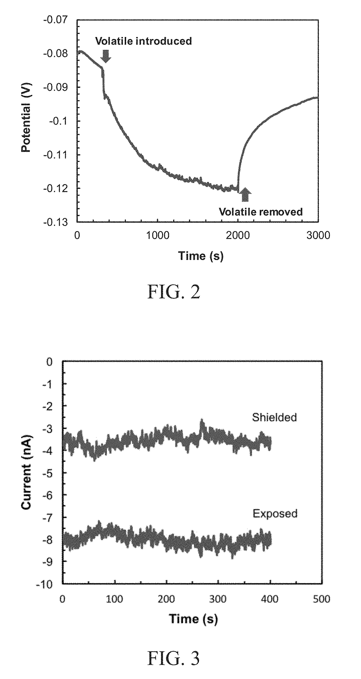
[0062]The open circuit potential (OCP) of the fuel-cell based sensor in the presence of isoflurane was examined and the results are as shown in FIG. 2. An isoflurane cloud was introduced to the sensor system after 500 s of OCP scanning. Amperometric studies were completed with the sensor exposed and shielded to isoflurane vapor (FIG. 3). The effect of isoflurane vapor concentration on the current measured by the senor was also investigated.

[0063]As shown in FIG. 2, the OCP deviated 40 mV from the point of introducing the isoflurane cloud, indicating a potential difference was resulted due to the redox chemical reactions described herein. After removing the volatile cloud, the OCP signal of the sensor gradually reached a steady state (see also FIG. 4).

[0064]The effect of concentration of isoflurane on the current measured by the sensor can be seen in FIG. 5. A linear response was observed when the concentration of the isoflur...


PUM

PropertyMeasurementUnit
thicknessaaaaaaaaaa
thicknessaaaaaaaaaa
temperatureaaaaaaaaaa

Abstract

Devices and methods of making and using the device for the non-invasive detection of volatile anesthetics are provided. The devices are capable of measuring the concentration of volatile anesthetics transdermally and in a non-invasive manner. The devices and methods can be applied in detection of volatile anesthetics in samples collected from human skin perspiration.

Description

BACKGROUND OF INVENTION[0001]Volatile anesthetics are a family of halogenated ethers that can quickly evaporate and thereby be inhaled by patients in need of such treatment. The effects of anesthesia primarily depend upon the concentration of anesthetics administered at the site of action. Most volatile anesthetics are administered in gaseous form to patients via a closed or open breathing circuit involving, for example, an anesthetic mask, a laryngeal mask airway, or an endotracheal tube. The effectiveness of volatile anesthetics delivered via methods described above cannot be directly evaluated in the brain of a patient; instead, other methods that include, for example, measuring the concentration transdermally, must be employed.[0002]Currently-available technologies for measuring transdermal content of volatile anesthetics have been limited to laboratory setups, which can be complex and non-transferrable to portable devices for clinical uses. Furthermore, these methods lack stabi...

Claims


Application Information

Patent Timeline
Patent Type & Authority Applications(United States)
IPC IPC(8): A61B5/1477H01M8/1004H01M8/04858H01M8/04537H01M4/86G01N27/407G01N33/94A61B5/145A61B10/00A61B5/00
CPCA61B5/1477H01M8/1004H01M8/04873H01M8/04582H01M4/8621G01N27/4074A61B5/6893G01N33/9486A61B5/14517A61B10/0064A61B5/742A61B5/6807G01N27/4076A61B5/14532A61B5/14542A61B5/14546A61B5/6804A61B5/681G01N33/0049G01N33/948H01M2008/1095Y02E60/50
Inventor UMASANKAR, YOGESWARANBHANSALI, SHEKHARPRETTO, ERNESTO A.
Owner FLORIDA INTERNATIONAL UNIVERSITY
Why Eureka
Try Eureka