Power inductor

Active Publication Date: 2018-12-20
MODA INNOCHIPS CO LTD
View PDF0 Cites 14 Cited by
  • Summary
  • Abstract
  • Description
  • Claims
  • Application Information

AI Technical Summary

Benefits of technology

[0031]In the power inductor in accordance to the exemplary embodiments, the body may be manufactured by mixing the magnetic pulverized material that is objected by pulverizing the magnetic material with the insulation material. Also, at least one magnetic layer in which the magnetic pulverized material is mixed may be formed within the body. Since the body is manufactured by using the magnetic pulverized material having magnetic permeability greater than that of the magnetic powder, the magnetic permeability of the body may be improved. Therefore, the overall magnetic permeability of the power inductor may be improved.
[0032]Also, since the parylene is applied on the coil pattern, the parylene having the uniform thickness may be formed on the coil pattern, and thus, the insulation between the body and

Problems solved by technology

Thus, the magnetic material may not realize high current properties that are required for the recent portable devices.
However, if the body is manufactured by using the metal, an eddy current loss and a hysteresis loss of a high frequency wave may in

Method used


Image

  • Power inductor
  • Power inductor
  • Power inductor

Examples


experimental example

[0086]A magnetic permeability and a quality factor (hereinafter, referred to as a Q factor) depending on adding of a magnetic pulverized material were measured. For this, a body was manufactured by using metal magnetic powder and a polymer. In an exemplary embodiment, the body was manufactured by using the metal magnetic powder, the magnetic pulverized material, and the polymer. First to third metal magnetic powder which respectively have mean particle size distributions D50 of 53 μm, 8 μm, and 3 μm were mixed with each other at a ratio of 8:1:1. That is, the first, second, and third metal magnetic powder were respectively mixed at contents of 80 wt %, 10 wt %, and 10 wt % with respect to 100 wt % of the total metal magnetic powder. Also, a material including Fe, Si, and Cr was used as the metal magnetic powder. Also, a body in accordance with the comparison example was manufactured by containing 4.25 wt % of epoxy with respect to 100 wt % of the metal magnetic powder.

[0087]Also, 0....

embodiments and modified example

Various Embodiments and Modified Example

[0091]FIG. 13 is a perspective view of a power inductor in accordance with still another exemplary embodiment.

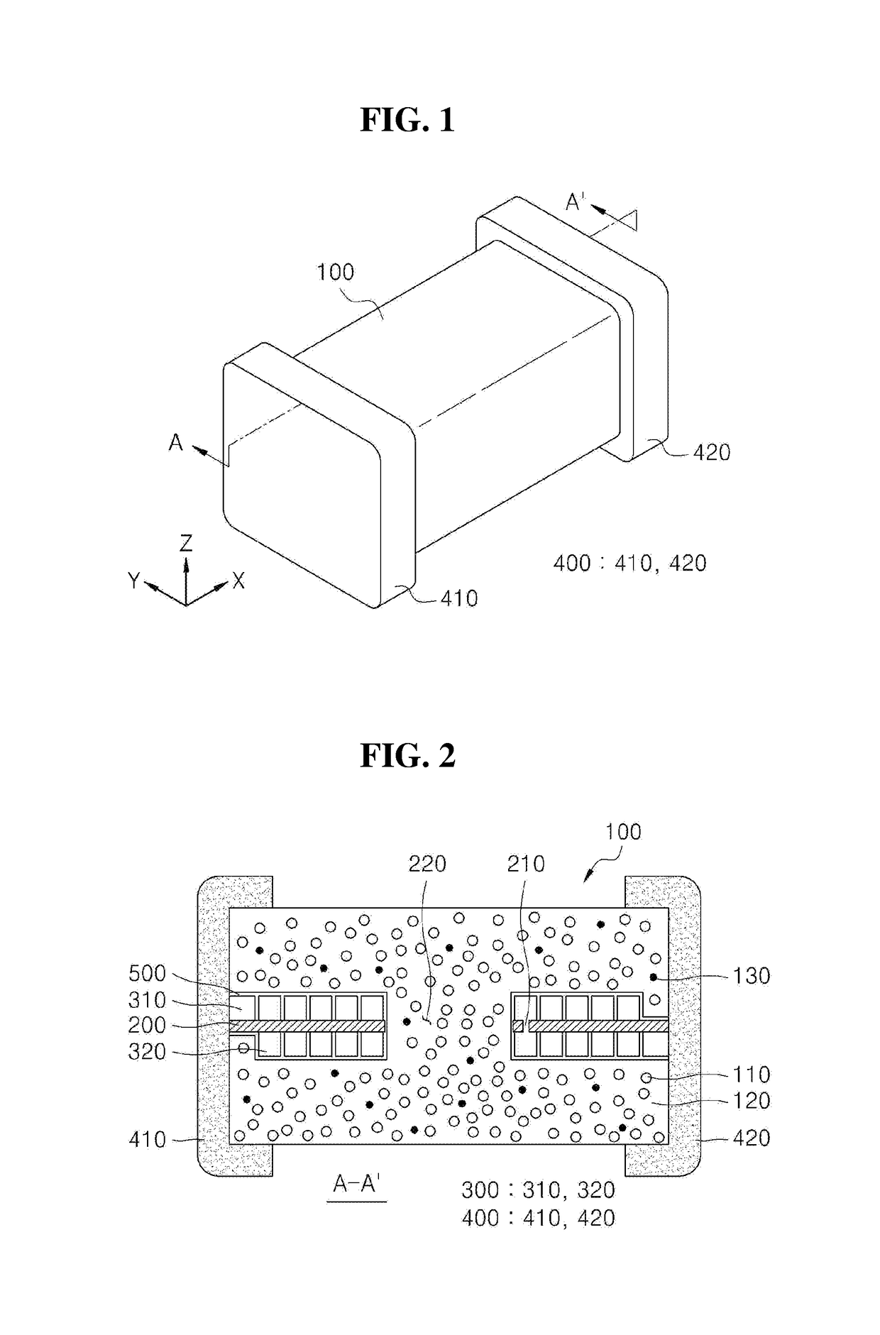
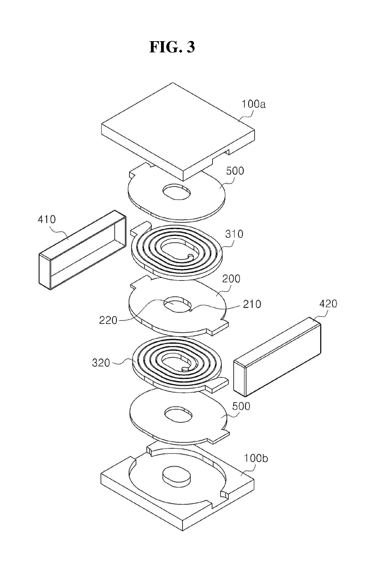
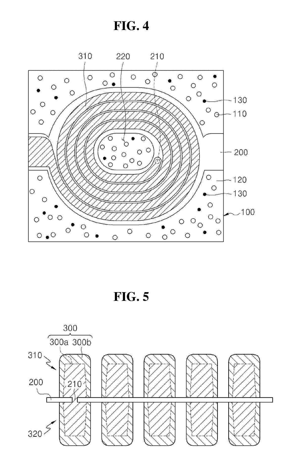
[0092]Referring to FIG. 13, a power inductor in accordance with another exemplary embodiment may include a body 100, a base material 200 provided in the body 100, coil patterns 310 and 320 disposed on at least one surface of the base material 200, external electrodes 410 and 420 provided outside the body 100, an insulation layer 500 provided on each of the coil patterns 310 and 320, and at least one magnetic layer 600 (610, 620) provided on each of top and bottom surfaces of the body 100. That is, another exemplary embodiment may be realized by further providing the magnetic layer 600 in an exemplary embodiment. Also, the body 100 may be formed by mixing a magnetic pulverized material and an insulation material 120, mixing metal magnetic powder and the insulation material 120, or mixing the magnetic pulverized material 110, the metal m...


PUM


Abstract

Provided is a power inductor. The power inductor includes a body, at least one base material disposed within the body, at least one coil pattern disposed on at least one surface of the base material, an insulation layer disposed between the coil pattern and the body, and an external electrode disposed outside the body and connected to the coil pattern. The body includes a magnetic pulverized material and an insulation material.

Description

TECHNICAL FIELD[0001]The present disclosure relates to a power inductor, and more particularly, to a power inductor having superior inductance properties and improved insulation properties and thermal stability.BACKGROUND ART[0002]A power inductor is mainly provided in a power circuit such as a DC-DC converter within a portable device. The power inductor is increasing in use, instead of an existing wire wound choke coil as the power circuit is switched at a high frequency and miniaturized. Also, the power inductor is being developed in the manner of miniaturization, high current, low resistance, and the like as the portable device is reduced in size and multi-functionalized.[0003]The power inductor according to the related art is manufactured in a shape in which a plurality of ferrites or ceramic sheets mode of a dielectric having a low dielectric constant are laminated. Here, a coil pattern is formed on each of the ceramic sheets. The coil pattern formed on each of the ceramic shee...

Claims


Application Information

Patent Timeline
IPC IPC(8): H01F1/057H01F17/04H01F17/00H01F27/29H01F27/32H01F27/255
CPCH01F1/057H01F17/04H01F17/0013H01F27/29H01F27/32H01F27/255H01F2017/048H01F27/008H01F27/22H01F27/292H01F27/324H01F1/33H01F1/0577H01F27/2804H05K2201/086
Inventor PARK, IN KILKIM, GYEONG TAEJUNG, JUN HOCHO, SEUNG HUNNAM, KI JOUNG
Owner MODA INNOCHIPS CO LTD
Why Eureka
Try Eureka