

Multi-clad Optical Fiber
a multi-clad, optical fiber technology, applied in the field of optical fibers, can solve the problems of long standing and unfulfilled need for high power, multi-clad, high beam quality optical fibers, etc., and achieve the effects of high na, low propagation loss, and high beam quality
- Summary
- Abstract
- Description
- Claims
- Application Information
AI Technical Summary
Benefits of technology
Problems solved by technology
Method used
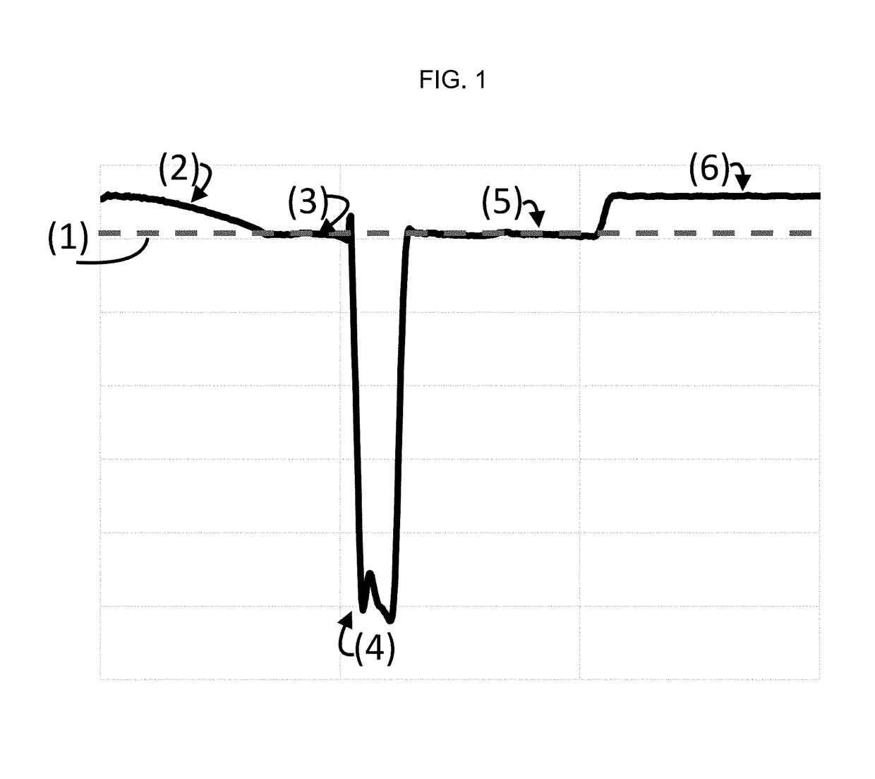
Image

Examples
example 1
[0055]
CompositionRegion in fiber(mol %)Region radius* (μm)GRIN coreSiO2 base20P2O5 / 2.5% @ center (parabolic)H2 / **Inner claddingSiO2 base11.25H2 / **Middle claddingSiO2 base6.25F / 12.7%H2 / **Outer claddingSiO2 base25***H2 / **Polymer coatingN / A60*region begins at end of previous region and ends and beginning of next region**H2 / O2 flame with H2 surplus, preform temperature ~1000° C., 6.2 days duration***V (gas flow or gas flows via bubblers): V - GeCL4 / V - SiCl4: 0.359 V - SF6 / V - SiCl4: 0.072 V - O2sur / V - SiCl4: 6.12
example 2
[0056]
CompositionRegion in fiber(mol %)Region radius* (μm)GRIN coreSiO2 base20P2O5 / 2.5% @ center (parabolic)H2 / **Inner claddingSiO2 base11.25H2 / **Middle claddingSiO2 base2.4 / 0.22****H2 / **Outer claddingSiO2 base25***H2 / **Polymer coatingN / A60*region begins at end of previous region and ends and beginning of next region**H2 / O2 flame with H2 surplus, preform temperature ~1000° C., 6.2 days duration***V (gas flow or gas flows via bubblers): V - GeCL4 / V - SiCl4: 0.359 V - SF6 / V - SiCl4: 0.072 V - O2sur / V - SiCl4: 6.12****PCF region with air hole diameter / wall thickness listed
example 3
[0057]
CompositionRegion in fiber(mol %)Region radius* (μm)GRIN coreSiO2 base12.5P2O5 / 2.5% @ center (parabolic)H2 / **Inner claddingSiO2 base11.25H2 / **Middle claddingSiO2 base2.4 / 0.22****H2 / **Outer claddingSiO2 base25***H2 / **Polymer coatingN / A60*region begins at end of previous region and ends and beginning of next region**H2 / O2 flame with H2 surplus, preform temperature ~1000° C., 6.2 days duration***V (gas flow or gas flows via bubblers): V - GeCL4 / V - SiCl4: 0.359 V - SF6 / V - SiCl4: 0.072 V - O2sur / V - SiCl4: 6.12****PCF region with air hole diameter / wall thickness listed
PUM
 Abstract
Description
Claims
Application Information