
Electrochromic compound, electrochromic composition, and display element

a technology of electrochromic composition and compound, applied in the direction of instruments, non-metal conductors, conductors, etc., can solve the problems of poor visibility, difficult to use electronic paper devices, and difficulty in multi-color display with maintaining white reflectivity and contrast ratio, etc., to achieve the characteristic of sharp light absorption spectrum and less color remaining

Active Publication Date: 2019-01-31
RICOH KK
View PDF0 Cites 8 Cited by
  • Summary
  • Abstract
  • Description
  • Claims
  • Application Information

AI Technical Summary

Benefits of technology

The electrochromic compound enables high reflectivity and contrast ratio while maintaining vivid color display and rapid response speeds, addressing the limitations of existing technologies for electronic paper applications.

Problems solved by technology

In any of these systems, however, it is very difficult to perform multicolor display with maintaining white reflectivity and contrast ratio.
When the white reflectivity and contrast ratio are significantly reduced, the visibility becomes very poor, and therefore it is difficult to use such device as electronic paper.
PTL 1 and PTL 2 each disclose a reflecting color display medium, in an electrophoresis element of which color filters are formed, but it is clear that such display medium cannot provide excellent image quality even when color filters are formed in the display medium of low white reflectivity and a low contrast ratio.
Theoretically, use of this method does not lead to a solution for the aforementioned problems, and cannot realize both high white reflectivity and a high contrast ratio.
However, as the electrochromic display device performs coloring and bleaching using an oxidation-reduction reaction, the electrochromic display device has a disadvantage that a coloring-bleaching response speed is slow.
However, this is not necessarily sufficient.
Moreover, the styryl-based dyes listed in PTL 8, PTL 9, and PTL 10 display excellent yellow, magenta, and cyan, but these dyes have problems in stability of coloring and bleaching, or durability for repetitive use.
The phthalic acid-based compound disclosed in PTL 12 has a problem that such compound has a poor memory function.

Method used


Image

  • Electrochromic compound, electrochromic composition, and display element
  • Electrochromic compound, electrochromic composition, and display element
  • Electrochromic compound, electrochromic composition, and display element

Examples


example 1

[0092]According the following synthesis flows (a) and (b), the electrochromic compound represented by the structural formula (21) was synthesized.

Synthesis of Intermediate Product (21-1)

Synthesis Flow (a)

[0093]

[0094]A 100 mL three-necked flask was charged with 0.594 g (3.00 mmol) of 2,6-dichloroquinoxaline, 1.72 g (8.4 mmol) of 4-(4, 4, 5, 5-tetramethyl-1,3,2-dioxaborolan-2-yl)pyridine, 0.055 g (0.060 mmol) of tris(dibenzylideneacetone)dipalladium(0), and 0.053 g (0.144 mmol) of triicyclohexylphosphonium tetrafluoroborate, and was purged with argon gas. Thereafter, to the flask, 11 mL of 1,4-dioxane and 8 mL of a 1.27M-tripotassium phosphate aqueous solution, which had been degassed with argon gas, were added in this order, and the resultant was subjected to reflux for 4 hours at 100° C. Thereafter, the reaction solution was cooled to room temperature, and chloroform and a saturated salt solution were added to the reaction solution. The resulting solution was transferred into a sep...

example 2

[0106]An electrochromic compound [the compound represented by the structural formula (1) listed earlier] was synthesized by allowing the intermediate product 22-1 synthesized in Example 1 to react with 2 equivalents of ethyl bromide.

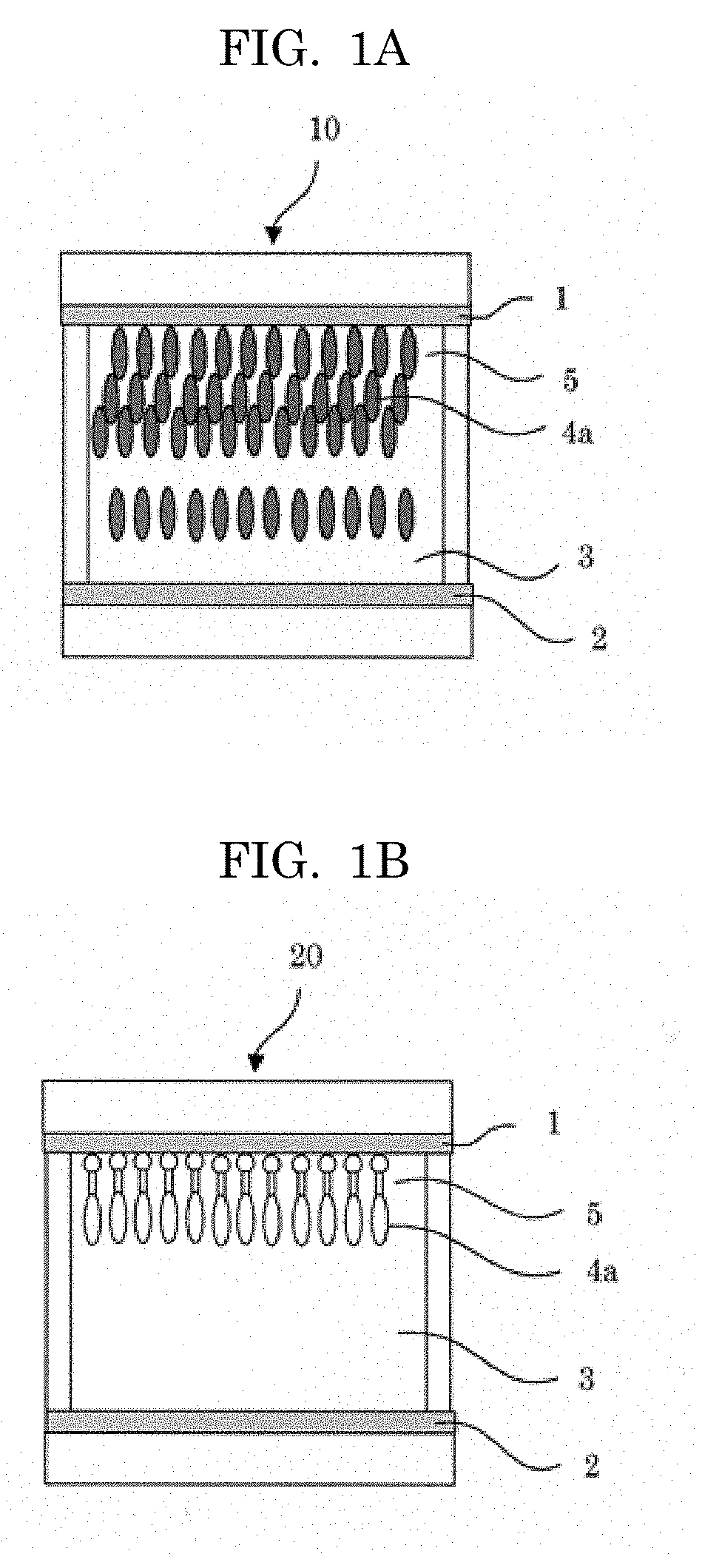
[0107]Next, in 2,2,3,3-tetrafluoropropanol, 1% by mass of the synthesized electrochromic compound [the compound represented by the structural formula (1)] and 5% by mass of tetrabutylammonium perchlorate serving as an electrolyte were dissolved, to thereby prepare an electrochromic compound solution. This electrochromic compound solution was enclosed in a cell prepared by bonding glass substrates each with an ITO electric conductive film in the size of 30 mm×30 mm (manufactured by GEOMATEC Co., Ltd.) together as a display substrate and a counter substrate via a spacer having a thickness of 75 μam, to thereby produce an electrochromic display element. The structure of the electrochromic display element is presented in FIG. 1.

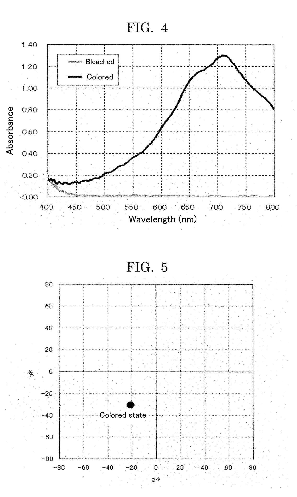
[0108]When a voltage of 3 V wa...

example 3

[0109]An electrochromic compound (Ex.-3) was synthesized in accordance with the following scheme.

(a) Synthesis of Intermediate Product (1,5-dimethoxy-2,6-di(4-pyridyl)naphthalene)

[0110]A 50 mL-flask was charged with 0.658 g (1.90 mmol) of 2,6-dibromo1,5-dimethoxynaphthalene, 1.560 g (7.61 mmol) of 4-(4,4,5,5-tetramethyl1,3,2-dioxaborolan-2-yl)pyridine, 70 mg (0.076 mmol) of tris(dibenzylideneacetone)dipalladium(0), and 67 mg (0.182 mmol) of tricyclohexylphosphine tetrafluoroborate, and then purged with argon. Thereafter, 2.16 g of tripotassium phosphate, 7 mL of water, and 7 mL of 1,4-dioxane were added to the flask, and the resulting mixture was heated and stirred for 18 hours at 95° C. After cooling the reaction solution to room temperature, the precipitated solids were collected through filtration, and then were washed with ethanol and ethyl acetate, to thereby obtain 0.543 g of a target product as colorless crystals.

(b) Synthesis of Electrochromic Compound (Ex.-3)

[0111]A 25 mL-f...


PUM

PropertyMeasurementUnit
timeaaaaaaaaaa
specific surface areaaaaaaaaaaa
room temperatureaaaaaaaaaa

Abstract

To provide an electrochromic compound, represented by the following general formulawhere X1, X2, X3, X4, X5, X6, X7 and X8 are each independently a hydrogen atom or a monovalent substituent; R1 and R2 are each independently a monovalent substituent; A− and B− are each independently a monovalent anion; and Y is represented by the following general formula (II) or (III):where X9, X10, X11, X12, X13, X14, X15, X16, X17, and X18 are each independently a hydrogen atom or a monovalent substituent.

Description

[0001]This is a divisional of application Ser. No. 14 / 433,176, filed Apr. 2, 2015, which is the National Stage of International application no. PCT / JP2013 / 080363, filed Nov. 1, 2013 which claimed priority to Japanese patent application nos. 2012-241679, filed Nov. 1, 2012, and 2013-096261, filed May 1, 2013, of which all of the disclosures are incorporated herein by reference in their entiretiesTECHNICAL FIELD[0002]The present invention relates to an electrochromic compound, and an electrochromic composition, both of which colors in cyan as they are colored, and relates to a display element using the electrochromic compound or the electrochromic composition.BACKGROUND ART[0003]As for an electronic medium replacing paper, developments of electronic paper have been recently actively carried out.[0004]The electronic paper has characteristics that the display device thereof is used like paper, and therefore requires properties different from conventional display devices, such as CRT and...

Claims


Application Information

Patent Timeline
Patent Type & Authority Applications(United States)
IPC IPC(8): C07F9/6558C09K9/02G02F1/15C07D401/14C07F7/08C07F9/58C07D401/10G02F1/1503
CPCG02F1/1503C09K9/02C09K2211/1007G02F2203/02C09K2211/1029C07D401/14C07F7/0836C09K2211/1044C09K2211/1011C07F9/58C07D401/10C07F9/65583
Inventor SAGISAKA, TOSHIYATAKAHASHI, HIROYUKIOKADA, TAKASHIHIRANO, SHIGENOBUYASHIRO, TOHRUFUJIMURA, KOHNAIJO, YOSHIHISAOKADA, YOSHINORITSUJI, KAZUAKIKIM, SUKCHANYUTANI, KEIICHIROHHORIUCHI, TAMOTSUINOUE, MAMIKO
Owner RICOH KK
Learn More