Active cooling of additive manufacturing process

a technology of additive manufacturing and active cooling, which is applied in the direction of manufacturing tools, soldering devices, auxillary welding devices, etc., can solve the problems of affecting the cooling rate of the structure, affecting the underlying structure of the built piece, and degrading the physical properties of the built pi

Active Publication Date: 2019-02-14
FORMALLOY LLC
View PDF5 Cites 12 Cited by
  • Summary
  • Abstract
  • Description
  • Claims
  • Application Information

AI Technical Summary

Problems solved by technology

An issue with all heat-based manufacturing processes is the effect of the heat on the underlying structure of the built piece.
For example, the amount of heat imparted on a build piece may affect the underlying grain structure of the build piece in a way that degrades its physical properties, such as strength, resilience, finish, etc.
The residual heat of the heat-based manufacturing process effectively reduces the cooling rate of the structure, which results in elongated grain sizes as the cooling rate decreases.
Elongated grains typically result in reduced material strength when compared with smaller grain structures.
Hence, elongated grains are typically undesirable.
Running relatively high laser power levels on relatively small structures will result in elongated grains more quickly than when running relatively low laser power levels.
In order to achieve homogenous, small grain structures, traditional additive manufacturing processes significantly limit the laser power applied to the build piece and / or implement delays in the build-up process to allow the structure to cool naturally.
However, these methods of controlling the heat of the manufacturing process on surrounding structures results in a slower build process, and may also limit the types of materials that can be used in the additive manufacturing process.
For example, having to limit the laser power may ultimately limit the access to materials that require significantly higher heat to process.

Method used


Image

  • Active cooling of additive manufacturing process
  • Active cooling of additive manufacturing process
  • Active cooling of additive manufacturing process

Examples


example additive

Manufacturing System

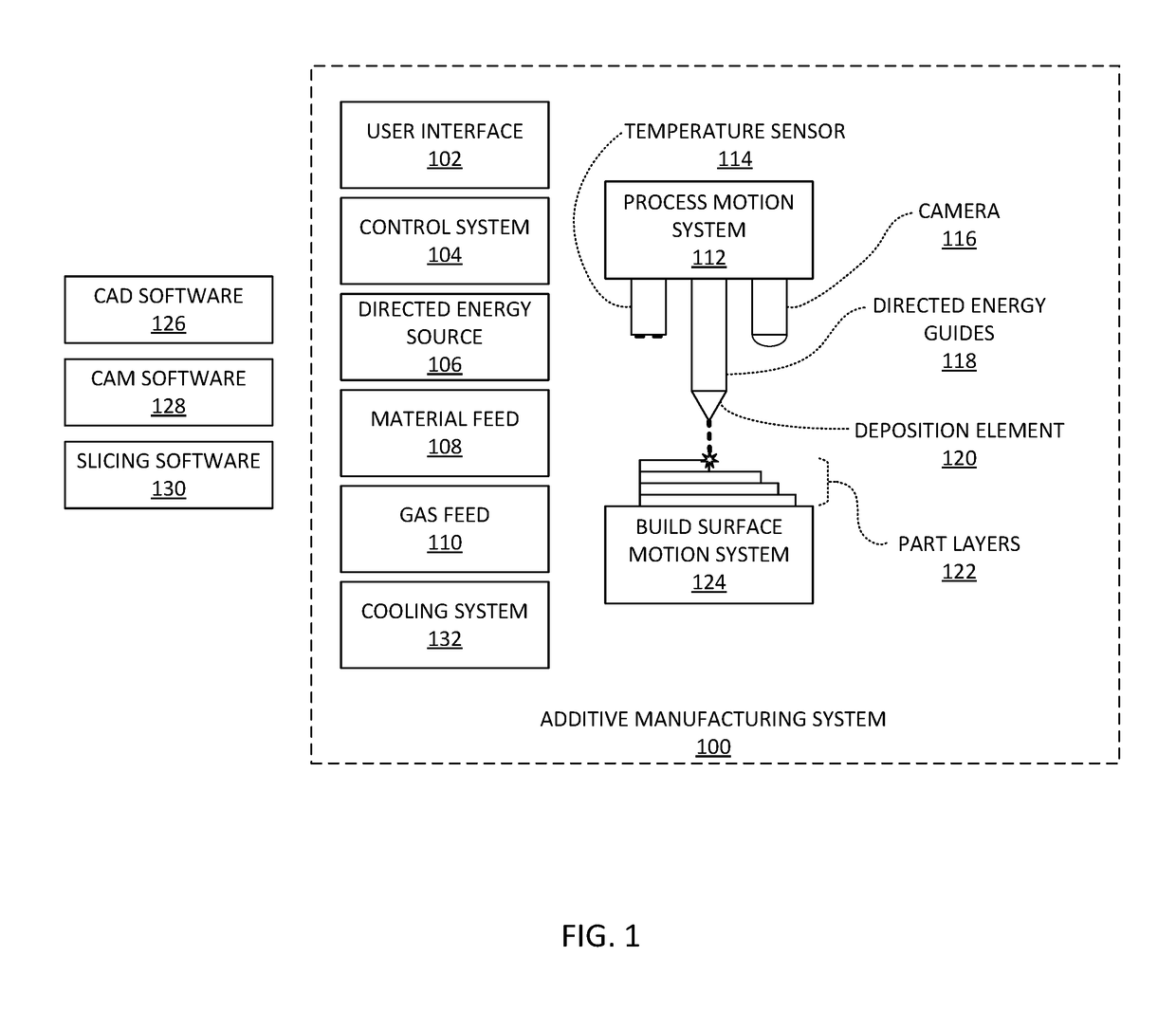
[0024]FIG. 1 depicts an example of an additive manufacturing system 100. Additive manufacturing system 100 includes a user interface 102. User interface 102 may be, for example, a graphical user interface comprising hardware and software controls for controlling additive manufacturing system 100. In some examples, user interface 102 may be integral with additive manufacturing system 100 while in other examples user interface 102 may be remote from additive manufacturing system 100 (e.g., on a remote computer such as a laptop computer or a personal electronic device).

[0025]Additive manufacturing system 100 also includes a control system 104. In this example, control system 104 is in data communication with user interface 102 as well as directed energy source 106, material feed 108, gas feed 110, process motion system 112, temperature sensor 114, camera 116, build surface motion system 124, and cooling system 132. In other examples, control system 104 may be in dat...


PUM

PropertyMeasurementUnit
temperatureaaaaaaaaaa
flow rateaaaaaaaaaa
energyaaaaaaaaaa

Abstract

Aspects of the present disclosure relate to. In one example, a method of controlling an additive manufacturing machine includes: measuring a first temperature of a part being processed by the additive manufacturing machine; determining that the first measured temperature exceeds a temperature threshold; activating an auxiliary gas flow; cooling the auxiliary gas flow with a cooling system; and directing the cooled auxiliary gas flow towards the part.

Description

CROSS-REFREENCE TO RELATED APPLICATION[0001]This application claims the benefit of U.S. Provisional Patent Application No. 62 / 543,811, filed on Aug. 10, 2017, the disclosure of which is incorporated herein by reference in its entirety.[0002]The present disclosure relates to additive manufacturing systems and methods. In particular, aspects of the present disclosure relate to systems and methods for actively cooling an additive manufacturing process, such as a laser metal deposition process, in order to improve structural characteristics of the piece built by the additive manufacturing process.[0003]Examples of commercially available additive manufacturing methods include extrusion-based methods (e.g., Fused Deposition Modeling (FDM)), fusing or binding from a powder bed based methods (e.g., Selective Laser Sintering (SLS), Selective laser melting (SLM), and Electron beam melting (EBM)), lamination methods, photopolymerization methods (e.g., stereo lithography), powder- or wire-fed d...

Claims


Application Information

Patent Timeline
Patent Type & Authority Applications(United States)
IPC IPC(8): B23K26/342B33Y30/00B33Y40/00B33Y50/02B23K26/03B23K26/14B23K26/70
CPCB23K26/342B33Y30/00B33Y40/00B33Y50/02B23K26/034B23K26/14B23K26/1437B23K26/703B23K37/003B33Y10/00B22F2203/11B22F2999/00Y02P10/25B22F10/322B22F12/20B22F12/70B22F10/368B22F10/85B22F12/53B22F10/22B22F12/90
Inventor RIEMANN, JEFFREY L.
Owner FORMALLOY LLC
Why Eureka
Try Eureka