Magnetic Diode in Artificial Magnetic Honeycomb Lattice

a magnetic diode and artificial honeycomb technology, applied in the field of macroscopy of magnetic artificial honeycomb lattices, can solve the problems of limited experimental efforts to realize the temperature-dependent magnetic correlations in the artificial honeycomb lattice, thermal fluctuations cannot induce spin flip or induce the development of a new phase, and the output power is reasonable small

Active Publication Date: 2019-02-21
UNIVERSITY OF MISSOURI
View PDF0 Cites 8 Cited by
  • Summary
  • Abstract
  • Description
  • Claims
  • Application Information

AI Technical Summary

Problems solved by technology

The experimental efforts to realize the temperature dependent magnetic correlations in an artificial honeycomb lattice is limited due to the constraints of known nanofabrication methods based on electron-beam lithography (EBL).
Therefore, thermal fluctuations cannot induce spin flip or induce the development of a new phase.
Also, the small sample size rules out the application of macroscopic probes necessary for magnetic and electrical measurements that are key to exploring the magnetic phases in artificial honeycomb lattice.
A need still exists for a magnetic system that exhibits unidirectional current biasing at a modest current (resulting in reasonably small output power) without the application of magnetic field.

Method used


Image

  • Magnetic Diode in Artificial Magnetic Honeycomb Lattice
  • Magnetic Diode in Artificial Magnetic Honeycomb Lattice
  • Magnetic Diode in Artificial Magnetic Honeycomb Lattice

Examples


example 1

Sample Fabrication

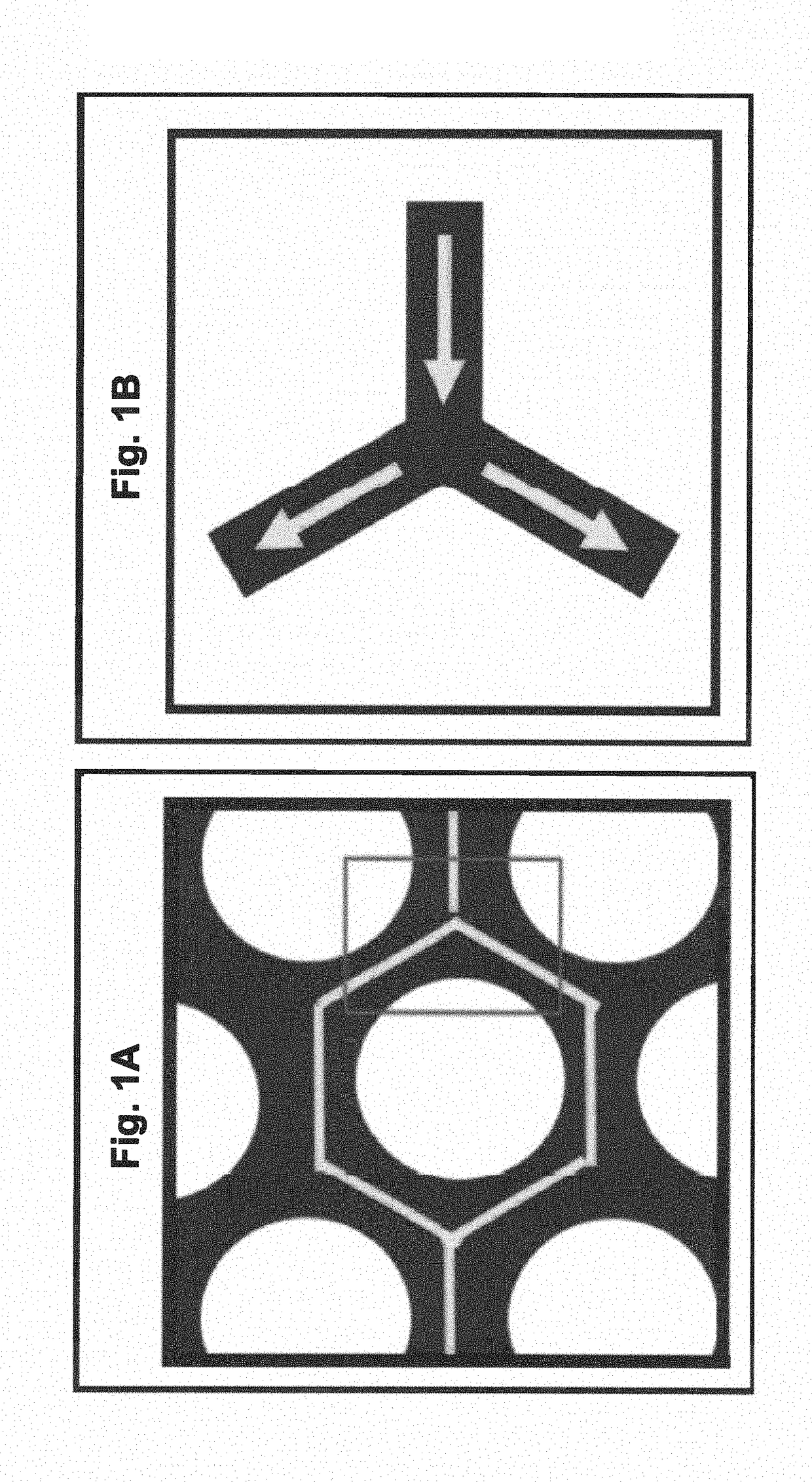
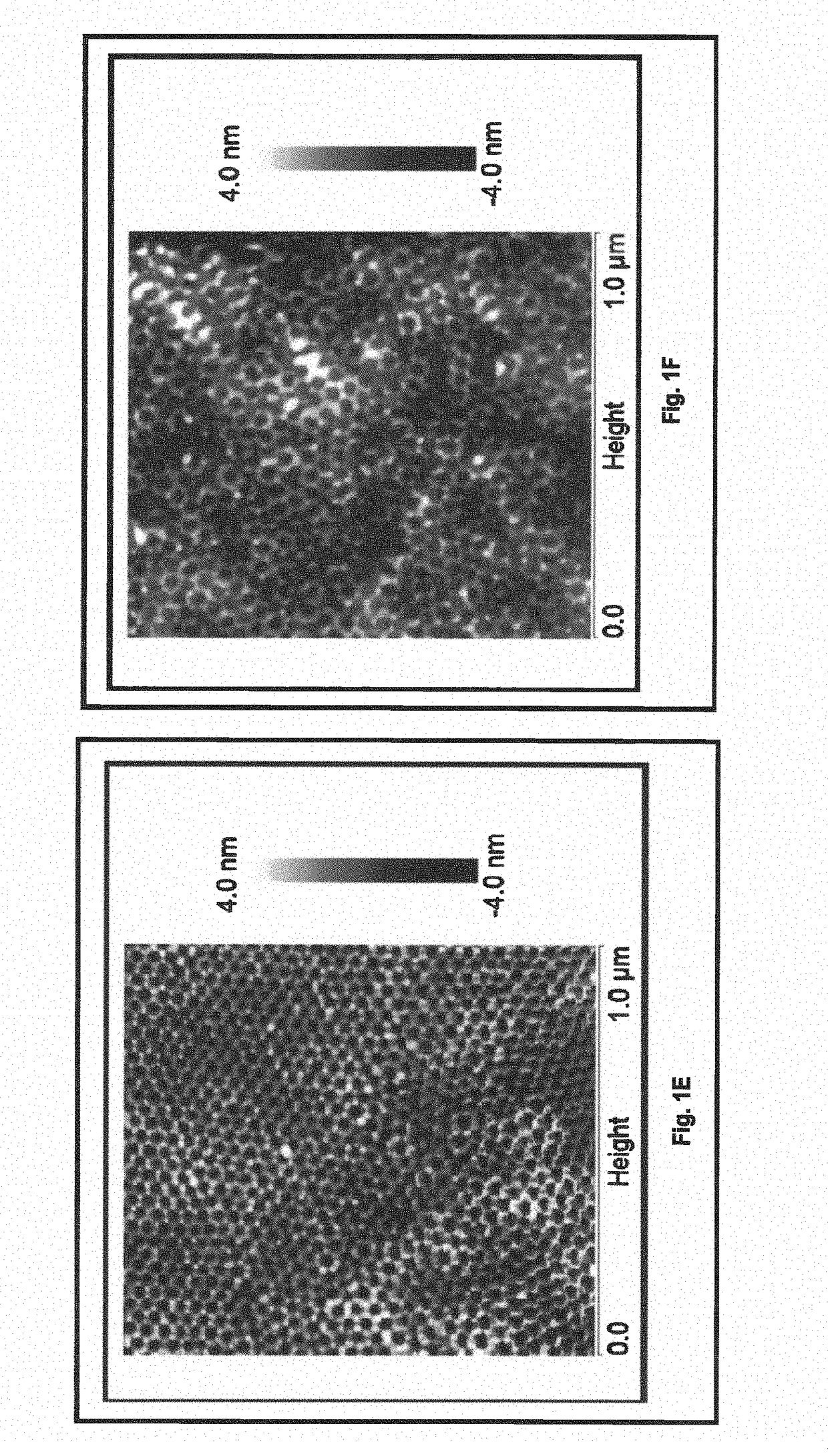
[0087]The sample fabrication process utilized diblock copolymer polystyrene(PS)-b-poly-4-vinyl pyridine (P4VP) of molecular weight 23 k Dalton with the volume fraction of 70% PS and 30% P4VP. At this volume fraction, the diblock copolymer tends to self-assemble in a hexagonal cylindrical structure of P4VP in the matrix of polystyrene. A 0.5% PS-b-P4VP copolymer solution in toluene was placed in a heat bath at 60° C. for 1.5 hours and stored in a standard refrigerator. The solvent was spin coated onto cleaned silicon wafers at 2500 rpm for 30 s and placed in vacuum for 12 hours to dry. The samples were solvent annealed at 25° C. for 12 hours in a mixture of THE / toluene (80:20 v / v) environment. The process results in the self-assembly of P4VP cylinders in a hexagonal pattern within a PS matrix, as shown schematically in Step 1 of FIG. 2. Submerging the samples in ethanol for 20 minutes releases the P4VP cylinders yielding a porous hexagonal template as shown in Step ...


PUM

PropertyMeasurementUnit
surface areaaaaaaaaaaa
widthaaaaaaaaaa
average center-to-center distanceaaaaaaaaaa

Abstract

A magnetic artificial honeycomb lattice comprising a multiplicity of connecting elements separated by hexagonal cylindrical pores, wherein:(a) the hexagonal cylindrical pores:(i) have widths that are substantially uniform and an average width that is in a range of about 15 nm to about 20 nm; and(ii) are substantially equispaced and have an average center-to-center distance that is in a range of about 25 nm to about 35 nm; and(b) the connecting elements comprise a magnetic material layer, and the connecting elements have:(i) lengths that are substantially uniform and an average length that is in a range of about 10 nm to about 15 nm;(ii) widths that are substantially uniform and an average width that is in a range of about 4 nm to about 8 nm; and(iii) a thickness of the magnetic material layer that is substantially uniform and an average thickness that is in a range of about 2 nm to about 8 nm; and(c) the magnetic artificial honeycomb lattice has a surface area, disregarding the presence of the hexagonal cylindrical pores, that is in a range in a range of about 100 mm2 to about 900 mm2.

Description

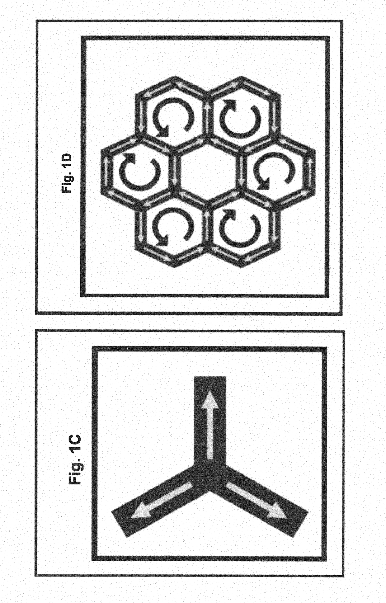
CROSS-REFERENCE TO RELATED APPLICATIONS[0001]The present application is a non-provisional application claiming the benefit of U.S. Ser. No. 62 / 505,856, filed May 11, 2017, which is incorporated herein by reference in its entirety.STATEMENT REGARDING FEDERALLY SPONSORED RESEARCH OR DEVELOPMENT[0002]This invention was made with government support under DE-SC0014461 awarded by the U.S. Department of Energy, Office of Basic Energy Sciences. The government has certain rights in the invention.FIELD OF THE INVENTION[0003]The invention is generally directed to macroscopic-size magnetic artificial honeycomb lattices, their manufacture, and use.BACKGROUND OF INVENTION[0004]An artificial magnetic honeycomb lattice that manifests a two-dimensional prototype of three-dimensional geometrically frustrated magnets yields a magnetism that has been intensively explored in recent times. The ice analogue of magnetism, spin ice, spin liquid, and exotic quantum mechanical properties of the resonant valen...

Claims


Application Information

Patent Timeline
Patent Type & Authority Applications(United States)
IPC IPC(8): H01L43/02H01F41/20H01F10/14H01F10/26H01L43/12H01L43/10H01F41/34
CPCH01L43/02H01F41/20H01F10/142H01F10/26H01L43/12H01L43/10H01F41/34H01F1/009G11C19/02G11C11/5607G11C11/161G11C11/16H10B61/10H10N50/80H10N50/01H10N50/85
Inventor SINGH, DEEPAK KUMARSUMMERS, BROCKDAHAL, ASHUTOSH
Owner UNIVERSITY OF MISSOURI
Why Eureka
Try Eureka