
Device for the contact-based simultaneous capture of prints of autopodia

a technology of autopodia and contact, applied in the field of devices for can solve the problems of reducing illuminance, requiring the use of complex mechanical components, and requiring calibration and assembly, and achieves the effects of increasing the degree of transmission, high reflectivity, and absorption of the absorption layer

Active Publication Date: 2019-02-28
JENETRIC
View PDF0 Cites 14 Cited by
  • Summary
  • Abstract
  • Description
  • Claims
  • Application Information

AI Technical Summary

Benefits of technology

The invention aims to improve a device used for capturing fingerprints by simultaneously capturing the prints of several autopodiae and using thicker protective bodies, such as cover glasses, while also optionally scanning documents. The device should have a flat contact surface and achieve image quality standards for all autopodiae placed on simultaneously. Additional illumination can be provided using individual light sources or a light guide, which helps to adapt the illuminance to the degree of transmission of the homogenizer. The light source can be switched off when additional illumination is used.

Problems solved by technology

In addition to the overall size and the weight, it is also disadvantageous that the use of complex mechanical components is necessary; moreover calibration and assembly are highly technically complex and time-consuming.
In the case of larger contact surfaces which are provided for the placement of several autopodia or a whole hand, however, the illuminance decreases with the result that the autopodia located at the edge are no longer correctly illuminated or their images are no longer completely usable due to a reduced contrast.
In order also to obtain a sufficient illuminance for the finger placed on furthest from the light source, a powerful light source is required which, however, leads to the fingers which are closest to the light source being illuminated with excessive intensity, which also has an adverse effect on the contrast or leads to overexposure of these areas.
When a microprism array is used, double images can form due to reflections in the light guide itself, furthermore parasitic scattered light from the surroundings can impair the image quality.
In the case of the methods described in U.S. Pat. No. 9,245,167 B2, the protective layer on the sensor layer has to be kept as thin as possible since otherwise diffuse light generates optical crosstalk, which reduces the resolution.
By this is meant the case where light from different angles of incidence strikes the same area of the contact surface and in the process records the same or very similar items of information about the finger placed on or not placed on at this specific point, but is also emitted at different angles of reflection due to the different angles of incidence and thus detected at various points, with the result that the resolution is impaired.
As already mentioned, prism devices are significantly larger and heavier than direct scanners, in particular when they are dimensioned for the simultaneous capture of several fingers.
The calibration has to be effected very accurately, which is technically complex.
The capture of documents is also not possible using this principle.
Although a robust encapsulation of the sensor / pixel structures can be achieved by means of such thin cover glass, the robustness against external mechanical influences is however reduced compared with thicker cover glasses.
Such devices are therefore less suitable for scanning documents.
Although glass with a thickness of less than 30 μm is commercially available and suitable for series production, it is however complex to process on large contact surfaces; in particular bubble-free optical bonding is challenging.
Transparent ceramics in this small thickness are not available in series production.
Capacitive devices on the other hand cannot be used for the capture of documents; in addition the sensors are usually not transparent with the result that to date neither user guidance nor user feedback has been realized in the capture surface by a display mounted below it.

Method used


Image

  • Device for the contact-based simultaneous capture of prints of autopodia
  • Device for the contact-based simultaneous capture of prints of autopodia
  • Device for the contact-based simultaneous capture of prints of autopodia

Examples


Embodiment Construction

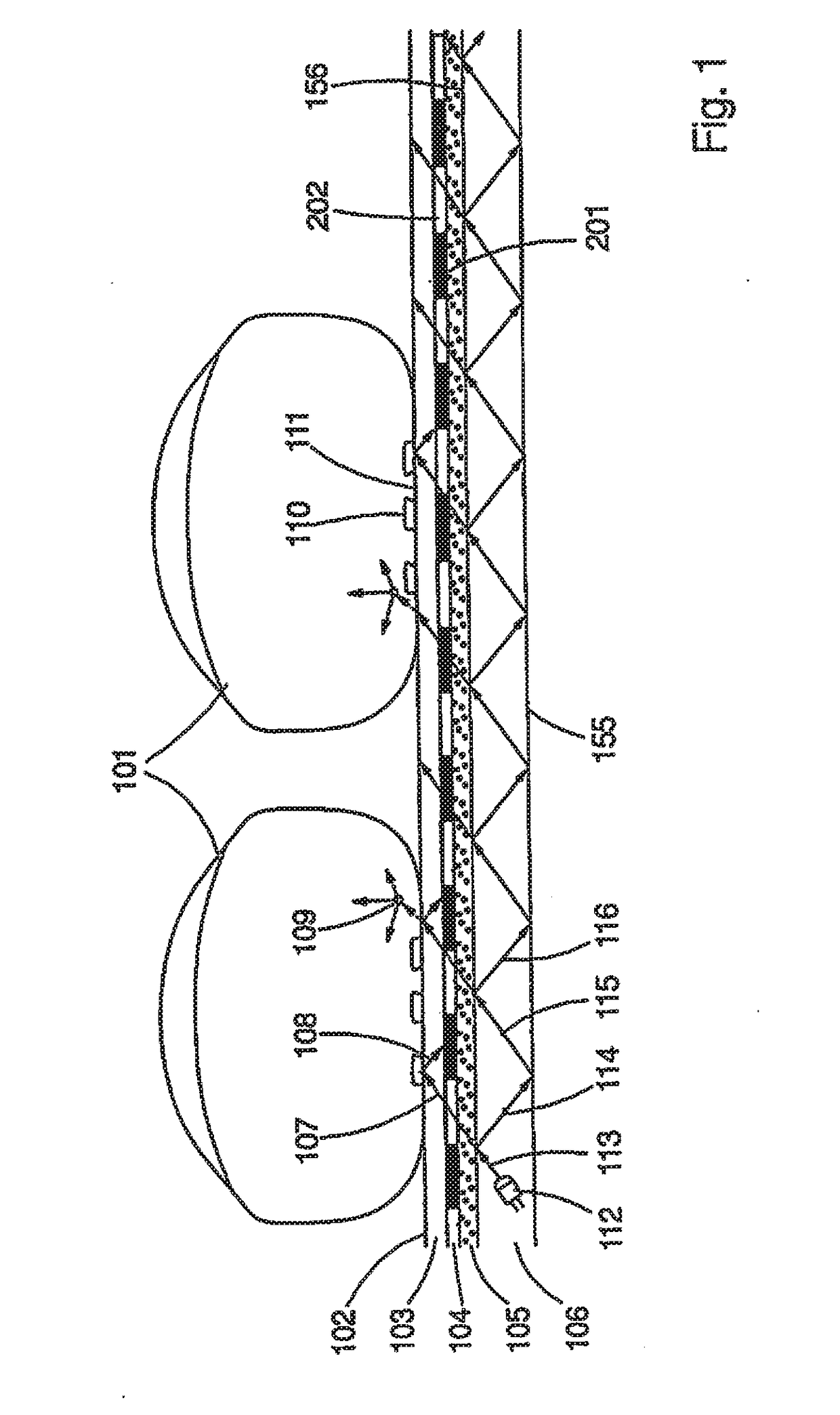
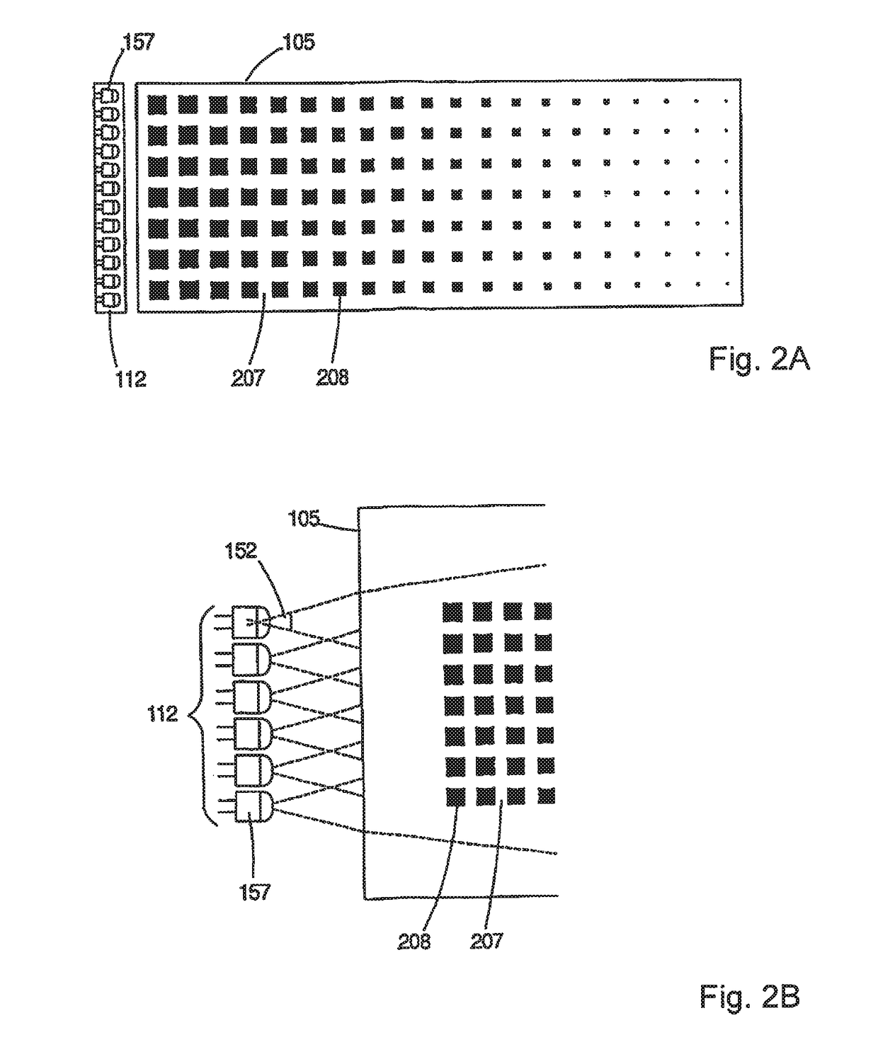
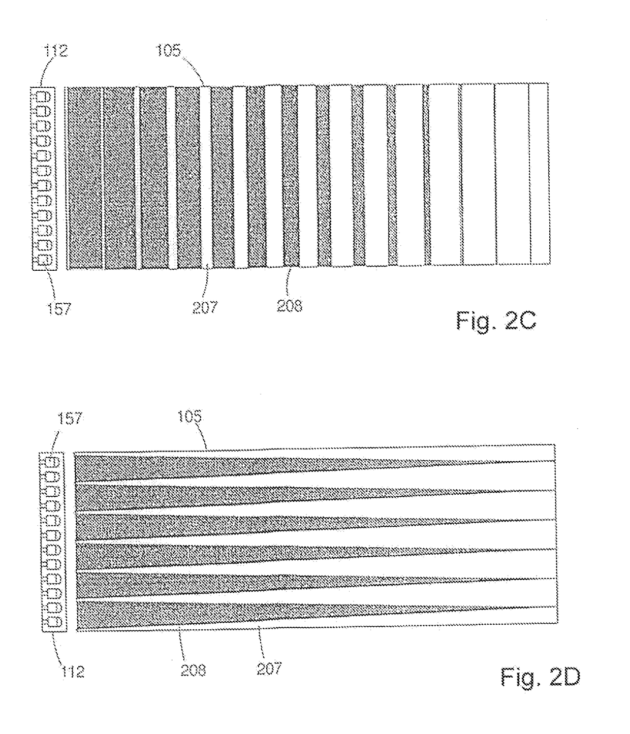
[0061]FIG. 1 shows the basic structure of a device for the contact-based simultaneous capture of prints of several areas of skin of human autopodia supplied with blood, by means of disturbed total internal reflection. A section of the device is shown along the direction in which light is emitted. By way of example here, two fingers 101 as autopodia are placed on a capture surface 102, which forms the closure of a protective body 103 of predefined thickness. The contact surface 102 here has a size which makes possible the simultaneous placement of several autopodia. Seen from the fingers 101, below the protective body 103 a sensor layer 104 is arranged which comprises light-sensitive sensor elements 201, arranged in the form of an array, which are also referred to as pixels in the following. The sensor elements 201 are designed to detect light of at least one predefined wavelength range—which comprises at least one wavelength. Passband areas 202 which are transparent for light of at ...


PUM


Abstract

A device for contact-based capture of human autopodial prints using disturbed total internal reflection, comprising a protective body with a contact surface, a sensor layer comprising light-sensor elements in an array for detecting light of a predefined wavelength range, and a light guide. Passband areas transparent for light of the predefined range are between the sensor elements. The light guide is transparent to light in the range and includes parallel lower and upper faces. The faces define a coupling-in surface for light emitted from a light source in a limited angular range around a preferred direction. Due to the directed angle of incidence, light entering the light guide is totally internally reflected at the faces. A mirror layer between the sensors and the guide reflects some light back into the light guide and transmits other light. Light exiting the guide is homogenized dependent upon a distance to the light source.

Description

PRIORITY CLAIM[0001]The present application claims priority to German Patent Application No. 10 2017 119 983.7, filed on Aug. 31, 2017, which said application is incorporated by reference in its entirety herein.FIELD OF THE INVENTION[0002]The invention relates to a device for the contact-based simultaneous capture of prints of several areas of skin of human autopodia supplied with blood, by means of disturbed total internal reflection.BACKGROUND OF THE INVENTION[0003]The identification and recording of people via biometric features is becoming increasingly important. Alongside other biometric features, fingerprints play an important role. On the one hand, there are systems which are used to verify biometric features in which there must therefore be a match with stored features, for example in order to enable entry or access control. Other systems are used for identification by searching and storing in reference databases, for example in the case of border controls at airports or in ...

Claims


Application Information

Patent Timeline
Patent Type & Authority Applications(United States)
IPC IPC(8): G06K9/00F21V8/00G06V30/144G06V10/141G06V10/147
CPCG06K9/0004G02B6/0065G02B6/0068G02B6/0031G06V40/10G06V10/12G02B6/0055G02B6/0061G02B6/0043G06V40/1324G06V40/1329G06V40/1318G06V10/141G06V10/147
Inventor REINHOLD, JOERGMORGENEIER, DIRKKRENZER, DANIELHILLMANN, JUERGENRIEHL, PHILIPPRICHTER, UNDINE
Owner JENETRIC
Learn More