Solid Dielectric for Rechargeable Energy Storage Capacitor

a technology of energy storage capacitor and solid dielectric, which is applied in the direction of fixed capacitor details, fixed capacitors, electrochemical generators, etc., can solve the problems of high toxicity, limited voltage range, and relatively large lithium batteries

Active Publication Date: 2019-02-28
NASA
View PDF0 Cites 1 Cited by
  • Summary
  • Abstract
  • Description
  • Claims
  • Application Information

AI Technical Summary

Problems solved by technology

However, in general, lithium batteries are relatively large, highly toxic, volatile, limited in terms of the number of charge / discharge cycles, limited in voltage range, and limited in terms of their charge / discharge rate.

Method used


Image

  • Solid Dielectric for Rechargeable Energy Storage Capacitor
  • Solid Dielectric for Rechargeable Energy Storage Capacitor
  • Solid Dielectric for Rechargeable Energy Storage Capacitor

Examples


Embodiment Construction

)

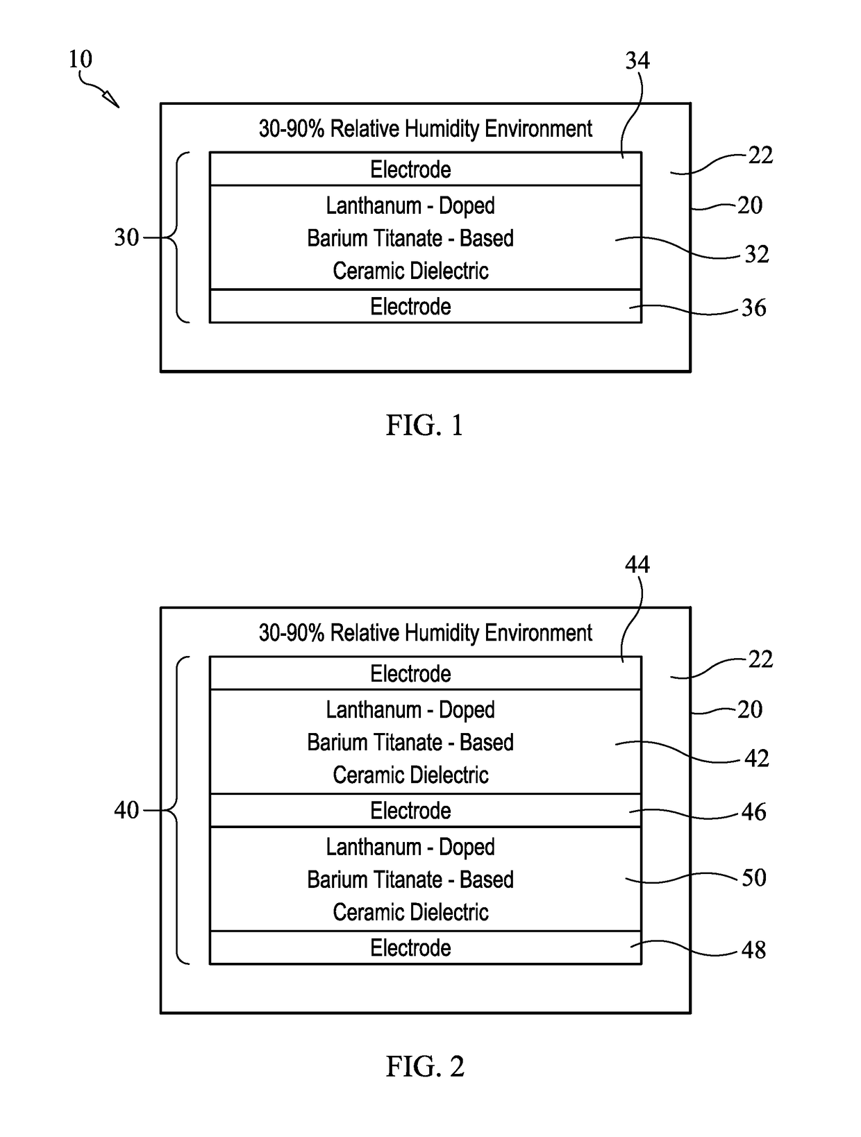
[0018]Referring now to the drawings and more particularly to FIG. 1, an energy storage system in accordance with an embodiment of the present invention is shown and is referenced generally by numeral 10. In general, energy storage system 10 is a rechargeable system that can be incorporated into a variety of electronic devices requiring a rechargeable energy storage source. It is to be understood that the drawing of energy storage system 10 is presented to show the essential elements thereof, but is not to scale.

[0019]Energy storage system 10 includes a casing 20 and an energy storage capacitor 30 disposed within casing 20. More specifically, casing 20 is a hermetically-sealed casing that can be made from a variety of materials to include, for example, plastics, ceramics, metals, or combinations thereof. Without departing from the scope of the present invention, casing 20 can be formed about capacitor 30 or assembled with capacitor 30 being placed therein during such assembly. In ei...


PUM

PropertyMeasurementUnit
thicknessaaaaaaaaaa
average grain diameteraaaaaaaaaa
weight percentaaaaaaaaaa

Abstract

A solid dielectric for an energy storage capacitor is a lanthanum-doped barium titanate-based ceramic material. A dopant is selected from the group consisting of lanthanum hydroxide and lanthanum oxide, and a co-dopant is an alkali hydroxide selected from the group consisting of potassium hydroxide, sodium hydroxide, rubidium hydroxide, and lithium hydroxide.

Description

[0001]This is a divisional application of co-pending application Ser. No. 15 / 473,364, “ENERGY STORAGE SYSTEM USING RARE EARTH AND HYDROXYL CO-DOPED CERAMIC IN HUMID ENVIRONMENT”, filed on Mar. 29, 2017.CROSS-REFERENCE TO RELATED PATENT APPLICATIONS[0002]This patent application is related to U.S. Pat. No. 9,987,658 entitled “METHOD OF MANUFACTURING A HUMIDITY SENSING MATERIAL”, application Ser. No. 15 / 473,322, filed Mar. 29, 2017, and owned by the same assignee as this patent application.ORIGIN OF THE INVENTION[0003]The invention described herein was made in the performance of work under a NASA contract and by an employee(s) of the United States Government and is subject to the provisions of Public Law 96-517 (35 U.S.C. § 202) and may be manufactured and used by or for the Government for governmental purposes without the payment of any royalties thereon or therefore. In accordance with 35 U.S.C. § 202, the contractor elected not to retain title.BACKGROUND OF THE INVENTION1. Field of ...

Claims


Application Information

Patent Timeline
Patent Type & Authority Applications(United States)
IPC IPC(8): H01G4/30H01G4/12H01G4/005H01G4/224C04B35/468
CPCH01G4/1227H01G4/005C04B2235/3227C04B2235/96H01G4/224H01G4/30C04B35/4682C04B2235/3236C04B2235/3215C04B35/6262C04B2235/3201C04B2235/3203C04B2235/36C04B2235/5436C04B2235/5445C04B2235/5454C04B2235/656H01G4/38Y02E60/50H01M6/185H01M8/0217
Inventor ROLIN, TERRY D.SMALL, IAN K.HILL, CURTIS W.
Owner NASA
Why Eureka
Try Eureka