
Method of forming internal stress control film

a technology of internal stress and control film, which is applied in the direction of vacuum evaporation coating, coating, sputtering coating, etc., can solve the problems of inability to realize the time of forming the thin film, and the technology of separately manufacturing a thin film having these two types of internal stress (compressive stress and tensile stress), and achieves high film density and increase the value of bias applied.

Active Publication Date: 2019-03-07
ULVAC INC
View PDF6 Cites 0 Cited by
  • Summary
  • Abstract
  • Description
  • Claims
  • Application Information

AI Technical Summary

Benefits of technology

The patent text describes a method for controlling internal stress in a film formed on a surface of an object using a sputtering method. By applying a weak bias to the object and setting a threshold pressure for the process gas, a strong tensile stress film can be obtained. Increasing the bias applied can change the stress from tensile to compressive while maintaining high film density. The method also involves stably manufacturing a titanium nitride film with a film density of 4.6 or more and having film stress on the tensile side. The technical effects of this method are improved control over internal stress in films, resulting in higher quality and more reliable performance.

Problems solved by technology

However, a technology for separately manufacturing a thin film having these two types of internal stresses (compressive stress and tensile stress) simply by changing fabrication conditions at the time of forming the thin film has not been realized.

Method used


Image

  • Method of forming internal stress control film
  • Method of forming internal stress control film
  • Method of forming internal stress control film

Examples


example 1

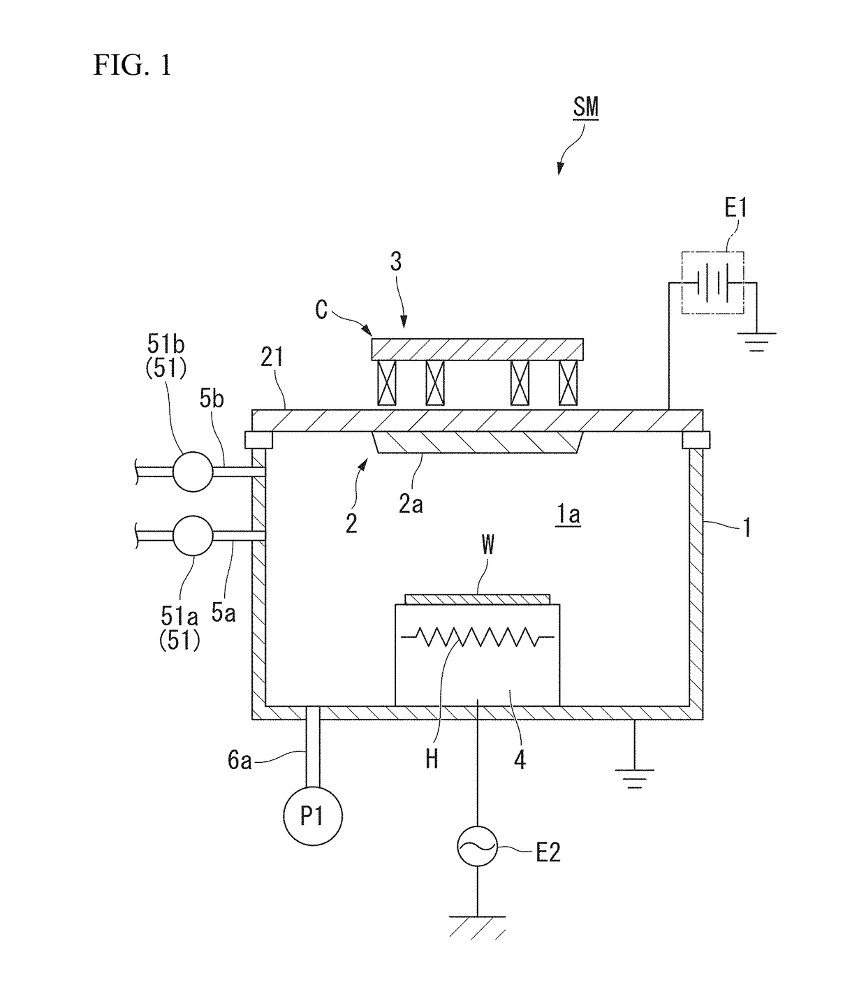
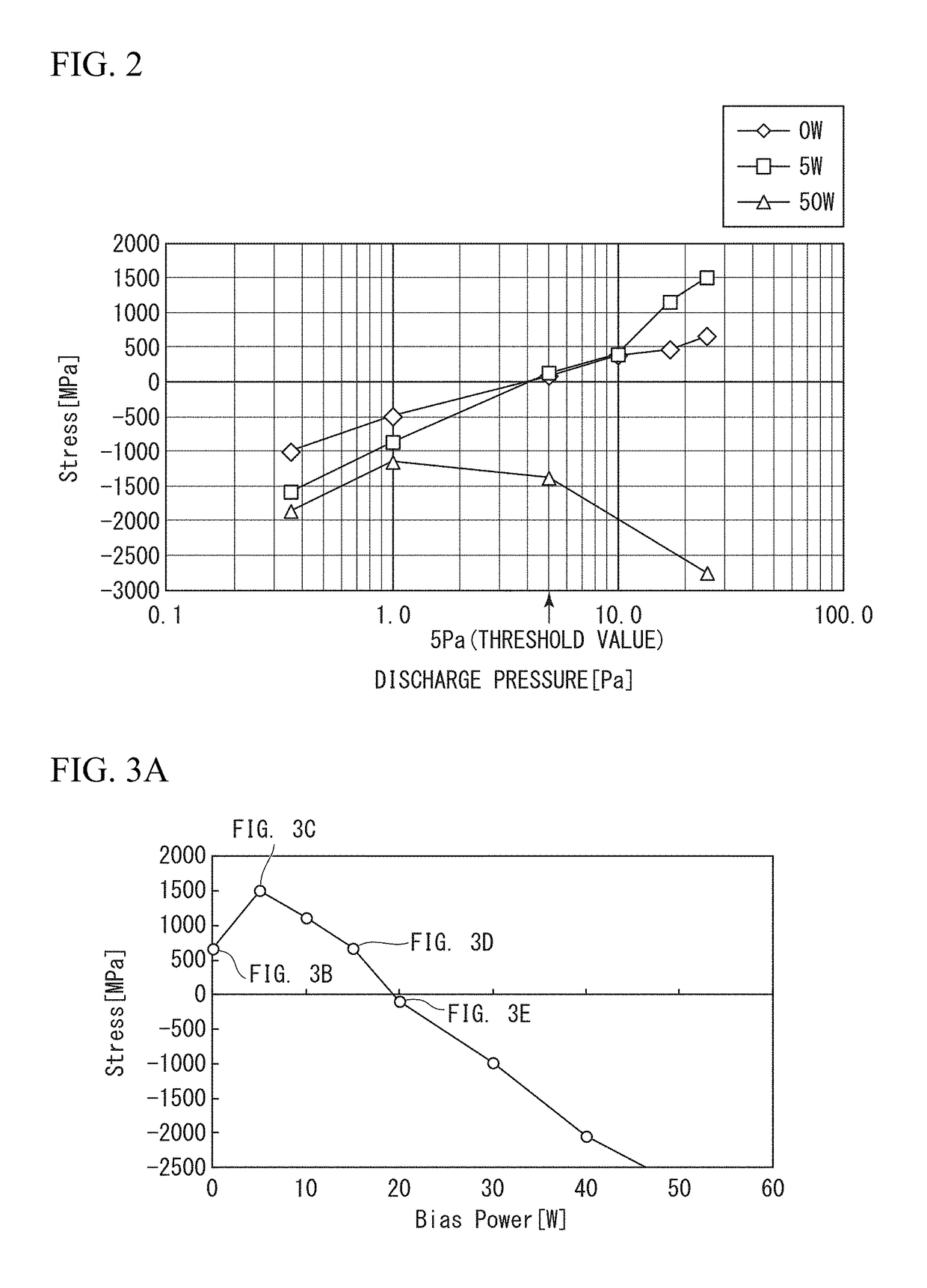
[0076]In the present example, the sputtering apparatus SM of FIG. 1 was used, and a pressure (discharge pressure) at the time of forming a thin film on an object to be processed (the substrate W made of a silicon wafer) was changed between 0.35 and 25 Pa to form a titanium nitride film (thickness: 20 nm). At that time, a bias BS dependence property was investigated by changing the bias BS applied to the substrate W (3 conditions: 0 W, 5 W, and 50 W). The result is shown in FIG. 2, which is a graph showing a relationship between a pressure (discharge pressure) and film stress at the time of forming a thin film.

[0077]From FIG. 2, the following points became clear.

[0078](A1) When the bias BS was 50 W, the fabricated titanium nitride film was not dependent on the discharge pressure and had film stress on the compressive (compressive) side with respect to the object to be processed. When the discharge pressure was more than 1 Pa, the film stress on the compressive (compressive) side show...

example 2

[0088]In the present example, film stress and film density under four pressure conditions (10.0, 17.0, 25.0, and 37.0 (Pa)) were investigated for a titanium nitride film. At that time, DC power (having a negative potential) applied to the target 2 was changed up to a maximum of five conditions (3.5, 7, 10.5, 14, 17.5, and 21 (kW)). In addition, the bias BS applied to the object to be processed was changed up to a maximum of 8 conditions (0, 2, 5, 10, 15, 20, 25, and 30 (W)).

[0089]Tables 1 to 3 are cases in which the pressure P of the process gas is 10.0 (Pa), among which Table 1 represents film stress, Table 2 represents film density, and Table 3 represents film deposition rates.

[0090]Tables 4 to 6 are cases in which the pressure P of the process gas is 17.0 (Pa), among which Table 4 represents film stress, Table 5 represents film density, and Table 6 represents film deposition rates.

[0091]Tables 7 to 9 are cases in which the pressure P of the process gas is 25.0 (Pa), among which T...


PUM

PropertyMeasurementUnit
Fractionaaaaaaaaaa
Fractionaaaaaaaaaa
Pressureaaaaaaaaaa

Abstract

A method of forming an internal stress control film on one surface of an object to be processed by a sputtering method, includes selecting a pressure of a process gas at the time of forming the internal stress control film from a pressure region higher than a threshold value of 5 (Pa) so that stress of the object to be processed when a bias is applied to the object to be processed becomes larger stress on a tensile side and the internal stress control film has higher density, as compared with stress in a case in which a bias is not applied thereto.

Description

TECHNICAL FIELD[0001]The present invention relates to a method of forming an internal stress control film in which a thin film having a desired film stress from a compressive side to a tensile side can be separately made while maintaining high film density.[0002]This application claims priority from Japanese Patent Application No. 2016-98158 filed on May 16, 2016, the contents of which are incorporated herein by reference in their entirety.BACKGROUND ART[0003]In a process of laminating a plurality of thin films to fabricate various types of devices, internal stress (internal stress) is generated on the thin films depending on fabrication conditions such as a material of a thin film, a thickness of the thin film, or a pressure or temperature at the time of forming the thin film, or depending on relative conditions between the thin film and an object to be processed constituting an underlayer of the thin film. As such internal stress (hereinafter also referred to as film stress), ther...

Claims


Application Information

Patent Timeline
IPC IPC(8): C23C14/34H01L21/285H01L21/033C23C14/06
CPCC23C14/345H01L21/285H01L21/0337C23C14/0641C23C14/0042C23C14/3492C23C14/35H01L21/32051H01L21/2855C23C14/0036C23C14/34C23C14/54H01L21/3205H01L21/768
Inventor NAKANO, KATSUAKIHIRAMATSU, DAISUKENUMATA, YUKINOBU
Owner ULVAC INC
Learn More