Production method for organic electroluminescent element

a production method and electroluminescent element technology, applied in the direction of electric lighting sources, solid-state devices, electric light sources, etc., can solve the problems of increasing driving voltage and increasing voltage, cracking or scraping of film layers and reducing the chance of recombination of holes and electrons

Active Publication Date: 2013-01-10
MERCK PATENT GMBH
View PDF8 Cites 2 Cited by
  • Summary
  • Abstract
  • Description
  • Claims
  • Application Information

AI Technical Summary

Benefits of technology

[0033]By the present invention, it is possible to provide an organic EL element which shows a small amount of voltage increase at the time of continued driving as well as a high luminescence efficiency and a low driving voltage.
[0034]Hereafter, although the details of each constituent element of an organic EL element of the present invention will be explained successively, the present invention is not limited to these.
[0035]In the present invention, it is characterized by the following in the production method of an organic EL element having an organic light emitting layer on a substrate: at least an organic light emitting layer is produced by a method including a wet process, and in a drying process of the organic light emitting layer, and it is heated while applying a tension to the substrate.
[0036]It is supposed that an organic EL element having an organic light emitting layer produced with the above-mentioned production method can reduce the chance of recombination of a hole and an electron by increasing a film density. Otherwise, it is supposed that the morphology of the film becomes similar to that of the film produced with a vacuum deposition method.
[0037]In the present invention, it is preferable to use a coating method such as: a spin coat method, a die coat method, an ink-jet method and a printing method, from the viewpoints of obtaining a uniform film and hardly producing a pinhole.
[0038]When a wet process is employed, it is preferable that the solvent after coating is removed as much as possible. It is possible to pass through a drying process. As a drying process, preferable methods are a heat drying method, a reduced pressure drying method and a heat-reduced pressure drying method. In particular, when a flexible substrate such as a resin is employed, the substrate may be deteriorated at too high temperature. Therefore, it is preferable to use a drying method in combination with a reduced pressure.

Problems solved by technology

However, an organic EL element produced with a wet process will not exhibit sufficient performance compared with an element produced with a vapor-depositing method.
In particular, it has a tendency of increased driving voltage and increased voltage at the time of continued driving.
However, by the method described in this Patent-document 1, there occurred a problem that a film layer was cracked or a film layer was scraped off due to the process by which the formed very thin film was contacted directly.
However, it is necessary to heat at a temperature higher than Tg of a composing material of an organic light emitting layer composition in this method.
There was a problem of difficulty in keeping the flexibility nature enabling to produce an organic electroluminescence element with a curved surface, which is one of the features of an organic electroluminescence element.
However, the layer will be destroyed, if the organic light emitting layer is stretched after being coated.

Method used


Image

  • Production method for organic electroluminescent element
  • Production method for organic electroluminescent element
  • Production method for organic electroluminescent element

Examples


example 1

Preparation of Organic EL Element 101

[0173]An anode was prepared by making patterning to a PET film of 100 mm×100 mm×0.3 mm (LUMILAR, made by TORAY Industries, Inc.) on which a 100 nm film of ITO (indium tin oxide) was formed. Thereafter, the above transparent support substrate provided with the ITO transparent electrode was subjected to ultrasonic washing with isopropyl alcohol, followed by drying with desiccated nitrogen gas, and was subjected to UV ozone washing for 5 minutes.

[0174]On this transparent support substrate thus prepared was applied a 70% solution of poly(3,4-ethylenedioxythiphene)-polystyrene sulfonate (PEDOT / PSS, Baytron P AI 4083 made by Bayer AG.) diluted with water with a spin coating method by adjusting the conditions so that a film thickness became 40 nm.

Then the coated film was dried at 130° C. for one hour to obtain a hole injection layer.

[0175]Subsequently, the substrate was fixed in a vacuum deposition apparatus, and the pressure of the vacuum tank was redu...

example 2

Preparation of Organic EL Elements 201 to 204

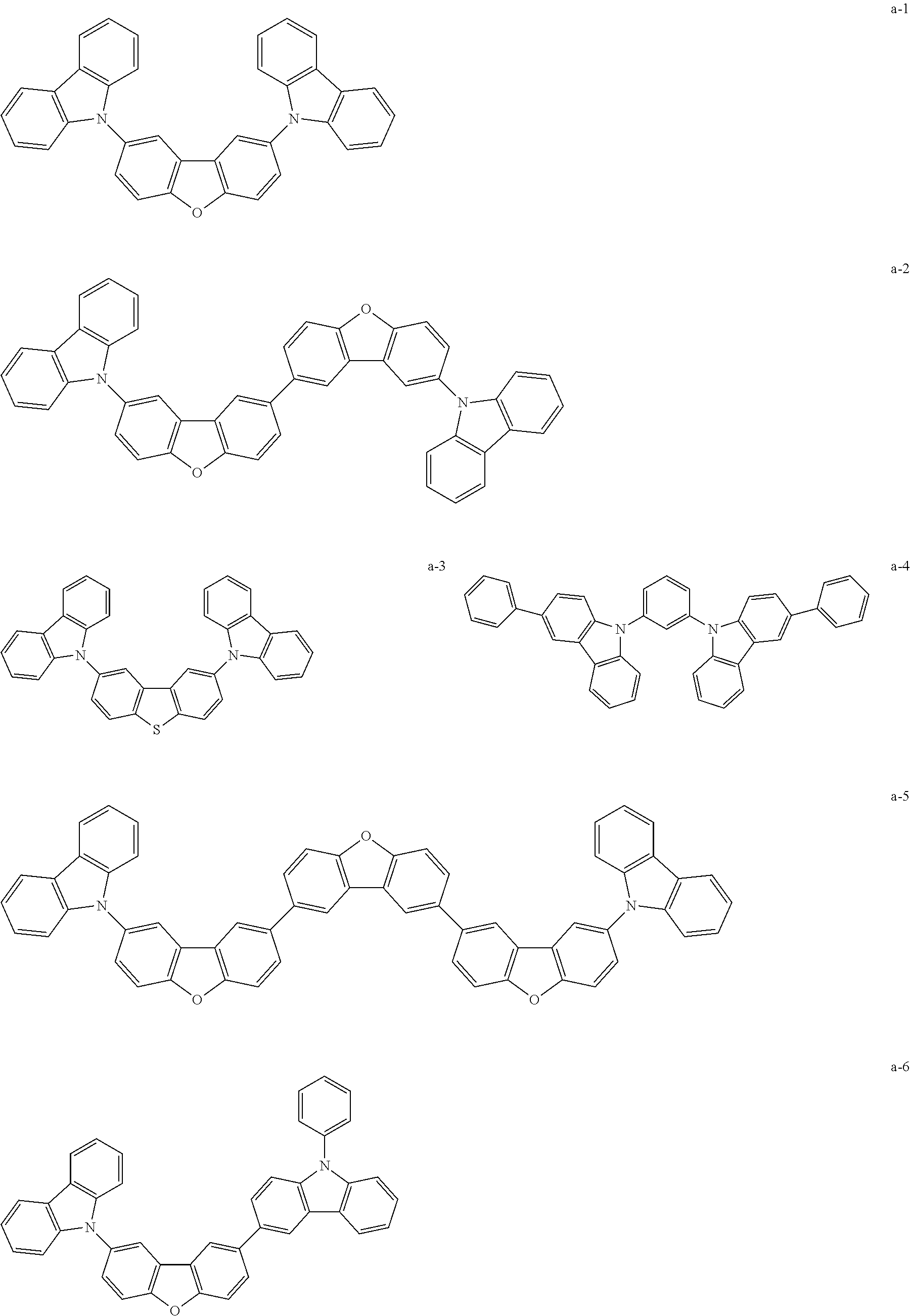
[0205]Organic EL element 201 was prepared in the same manner as preparation of Organic EL element 101, except that a light emitting host and a dopant each were replaced with the compounds shown in Table 2 so as to change an emission color to white, and the film thickness was made to be the value shown in Table 2. Further, Organic EL elements 202 to 204 each were prepared in the same manner as preparation of Organic EL elements 102 to 104, except that a light emitting host and a dopant each were replaced with the compounds used in Organic EL element 201 and the film thickness was made to be the value shown in Table 2. In addition, the used amounts of the compounds in the organic light emitting layer were made as follows, exemplified compound a-6: Dopant-1: Ir-1: Ir-4=5:24.2:0.3:0.4 by mass.

<

[0206]The prepared organic EL elements each were evaluated with respect to the items done in Example 1. Th...

example 3

Preparation of Organic EL Elements 303, 304 and 402

[0208]Organic EL elements 303 and 304 each were prepared in the same manner as preparation of Organic EL elements 203 and 204, except that no tension was applied during the constant rate drying in the drying step of the organic light emitting layer after coated, and the tension was applied to the 4 sides of the substrate during the decreasing rate drying: 2.8 N / m for Element 303; and 44 N / m for Element 304 as shown in Table 3.

[0209]Here, a stress to the substrate becomes 9.3 kPa when a tension of 2.8 N / m is applied, and a stress to the substrate becomes 145 kPa when a tension of 2.8 N / m is applied.

[0210]Further, Organic EL element 402 was prepared in the same manner as preparation of Element 203, except that one axis stretching was made with a tension of 1,500 N / m during a decreasing rate drying so as to stretch in an amount of 2 cm. When Organic EL element 402 was observed with a microscope, it was observed a crack on the coated la...


PUM

PropertyMeasurementUnit
temperatureaaaaaaaaaa

Abstract

Disclosed is a production method for an organic electroluminescent element that is provided with a substrate, an organic laminate with an organic light emitting layer that was formed by a method involving a wet process, and a pair of electrodes, wherein the method produces an organic electroluminescent element with high luminous efficiency, low driving voltage, and a minimal rise in voltage when continuously driven, by applying the coating liquid for said organic light emitting layer, and thereafter, in a drying process, heating the substrate while applying tension in a manner such that a stress that is less than the yield stress is applied to the substrate.

Description

TECHNICAL FIELD[0001]The present invention relates to a production method of an organic electroluminescence element produced by a method containing a wet process. In particular, the present invention relates to a production method of an organic electroluminescence element exhibiting a high light emitting efficiency with a low driving voltage and having a long lifetime with small increase of driving voltage after a prolonged continued driving.BACKGROUND[0002]It is known an electroluminescence device (hereinafter, referred to as an ELD) as an emission type electronic device. As a composing element of an ELD, there are cited an inorganic electroluminescence element (hereinafter, referred to as an inorganic EL element) and an organic electroluminescence element (hereinafter, referred to as an organic EL element). An inorganic EL element has been utilized mainly as a flat light source, however, it requires a high voltage of alternating current to drive an emission element.[0003]On the ot...

Claims


Application Information

Patent Timeline
Patent Type & Authority Applications(United States)
IPC IPC(8): H01L51/56
CPCH01L51/0003H01L51/0026H01L51/0037H01L51/0085H05B33/10H01L51/0072H01L51/50H10K71/12H10K71/40H10K85/1135H10K85/342H10K85/6572H10K50/00
Inventor ISHIDAI, HIROSHINAKAYAMA, TOMOYUKIFURUKAWA, SHUN
Owner MERCK PATENT GMBH
Why Eureka
Try Eureka