Flue gas condensation water extraction system

a technology of flue gas and water extraction system, which is applied in the direction of emission prevention, separation process, lighting and heating apparatus, etc., can solve the problems of low initial capital investment of the system and moderate water recovery cos

Active Publication Date: 2019-03-21
LIU CHUNXIAO
View PDF0 Cites 5 Cited by
  • Summary
  • Abstract
  • Description
  • Claims
  • Application Information

AI Technical Summary

Benefits of technology

[0003]The invention aims at overcoming the deficiencies of the prior art and provides a flue gas water condensation water extraction system, which can condense and recover a large amount of water in the flue gas, thereby solving the problem of huge water consumption in the wet desulfurization system.
[0005]The beneficial effects of the present invention include: on the basis of purifying the flue gas in the desulfurization absorption tower, the flue gas can be further purified by the flue gas purification condensation tower. The concentration of soot and the concentration of sulfur dioxide are further reduced. The phenomenon of gypsum entraining with desulfurization flue gas is completely eliminated. The water filling and draining system is used to automatically complete water filling during the initial startup of the system and water drainage during the initial shutdown of the system, so that the water extraction process of the flue gas condensing and extraction system has high reliability, completeness, and adaptability, and can automatically finish startup and shutdown of the system, and it can run with a long-term stability. The system can accomplish condensing and extraction of water from the flue gas after wet desulfurization treatment, providing a large amount of water for use in the production and significantly saving water resources. In addition, the initial capital investment of the system is low, and the cost for water recovery is moderate. The flue gas condensate extraction system has a smaller resistance on circulating water side and a moderate resistance on flue gas side, leading to a high efficiency in heat exchange between the flue gas and the condensate water.
[0008]The beneficial effects in adopting the above further embodiment include that the condensate water is introduced into the condensate storage tank, and when the water in the condensate storage tank reaches the overflow level, water will flow along the overflow pipeline into the underground water storage tank. The underground water storage tank achieves water volume adjustment functions and can be used, via a water pump, as water supply for the desulfurization process. The surplus water volume can also be used as water supply in the production processes. The underground water storage tank also helps keep the water level in the condensate storage tank no higher than the overflow level.
[0015]Beneficial effects of the above-described further solution include that the flue gas is dispersed in the sky, diluted and transported with winds over a long distance.
[0018]The beneficial effects of adopting the above further solution is that when the flue flapper door is fully open, the clean flue gas that has passed through the desulfurization absorption tower can enter the bypass flue, thereby bypassing the flue gas purification condensation tower to discharge into the chimney. When the flue gas purification condensation tower fails, the desulfurization absorption tower can still operate normally, and the flue gas can still complete the desulfurization purification.

Problems solved by technology

In addition, the initial capital investment of the system is low, and the cost for water recovery is moderate.

Method used


Image

  • Flue gas condensation water extraction system
  • Flue gas condensation water extraction system

Examples


example 1

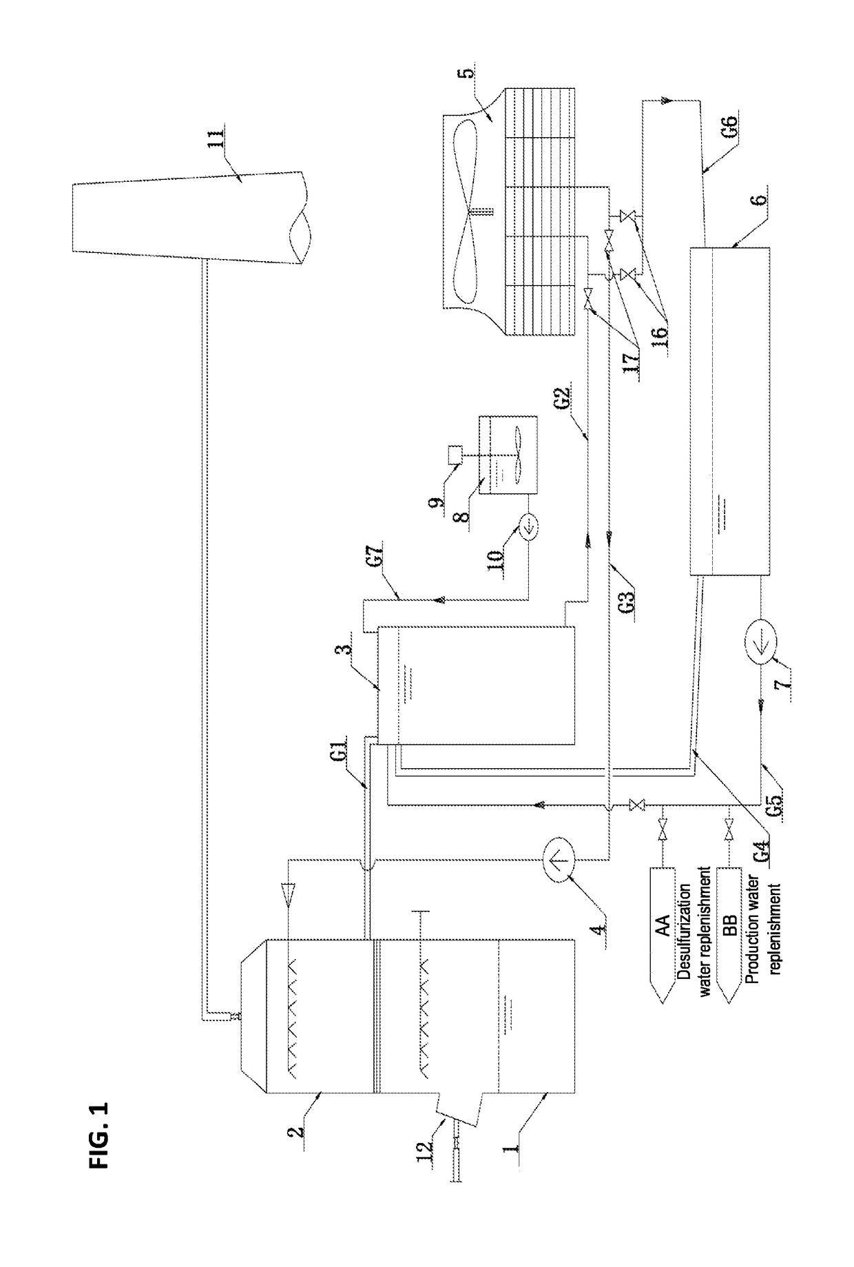
[0023]As shown in FIG. 1, a flue gas condensation extraction system comprises a flue gas condensation end (or a flue gas condensation terminal) system and a flue gas refrigeration source end (or a flue gas refrigeration source terminal) system. The flue gas condensation end system comprises a desulfurization absorption tower 1, a flue gas purification condensation tower 2, and a condensate storage tank 3. A flue gas inlet 12 is disposed on the desulfurization absorption tower. The flue gas purification condensation tower is disposed above the desulfurization absorption tower. The flue gas purification condensation tower is provided with a flue gas outlet, a water inlet, and a water outlet (drain). The flue gas refrigeration source end system comprises a cooling tower 5. The water outlet is connected to the condensate storage tank 3 via a condensate water descending pipe G1. The water inlet is connected with the cooling tower via a circulating water supply pipe G3. The circulating wa...

example 2

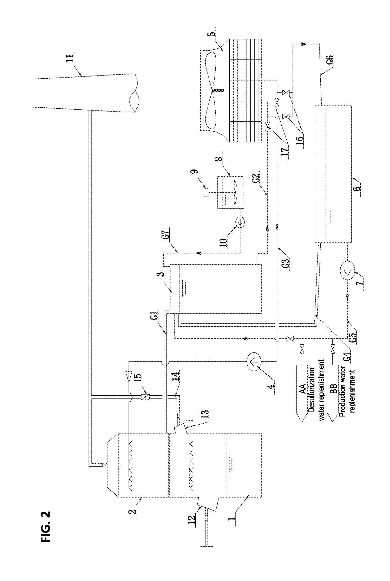
[0029]As shown in FIG. 2, a flue gas desulfurization outlet 13 is disposed on the desulfurization absorption tower. A bypass flue 14 is disposed at the flue gas desulfurization outlet. A flue baffle door 15 is disposed on the bypass flue. The outlet of the bypass flue is connected to the flue. When the flue baffle door is fully open, the clean flue gas that has passed through the desulfurization absorption tower can enter the bypass flue, thereby bypassing the flue gas purification condensation tower to discharge into the chimney. When the flue gas purification condensation tower fails, the desulfurization absorption tower can still function normally, and the flue gas can still be desulfurized and purified.


PUM

PropertyMeasurementUnit
liquid levelaaaaaaaaaa
temperatureaaaaaaaaaa
concentrationaaaaaaaaaa

Abstract

A flue gas condensation water extraction system includes a flue gas condensation-end system and a flue gas refrigeration source-end system. The flue gas condensation-end system includes a desulfurization absorption tower, a flue gas purification and condensation tower, and a condensed water storage tank. The flue gas purification and condensation tower is arranged above the desulfurization absorption tower. A flue gas outlet, a water inlet, and a water outlet are provided on the flue gas purification and condensation tower. The flue gas refrigeration source-end system includes a cooling tower. The water outlet is connected to the condensed water storage tank via a condensed water downcomer. The water inlet is connected to the cooling tower via a circulating water supply pipe. A condensation circulation water pump is provided on the circulating water supply pipe. The cooling tower is connected to the condensed water storage tank via a circulating water return pipe.

Description

BACKGROUND OF THE INVENTIONTechnical Field[0001]The invention relates to a flue gas condensation water extraction system, belonging to the technical field of flue gas water extraction.Background Art[0002]In the field of atmospheric pollutants control and flue gas desulfurization, the wet desulfurization process is a mature and reliable technology, with a high desulfurization efficiency and strong adaptability. It is the most widely used flue gas desulfurization technology. However, the wet desulfurization process consumes a large amount of water, which has become an increasingly prominent issue. Thermal power generation industry, chemical industry, and metal smelting industry generally use limestone-gypsum wet desulfurization technology for flue gas purification treatments. Due to the characteristics of the processes, the high-temperature flue gas carries a large amount of saturated water vapor and droplets during desulfurization treatments. The process consumes a lot of water reple...

Claims


Application Information

Patent Timeline
Patent Type & Authority Applications(United States)
IPC IPC(8): B01D5/00B01D53/00B01D53/18
CPCB01D5/0003B01D5/003B01D5/0051B01D5/0075B01D5/0087B01D53/005B01D53/18B01D53/1418B01D53/002B01D5/009B01D53/265B01D53/504F23J15/04B01D2251/304B01D2251/604B01D2251/606B01D2258/0283F23J2219/40F23J15/006F23J2215/20
Inventor LIU, CHUNXIAOYU, PEIDONGSHI, KAIGEHU, CHAOYOUXIU, LIJIECHEN, YONGDING, JIANBINGJIA, SHUANGYANHUO, XINGJIACAI, YOULIN
Owner LIU CHUNXIAO
Why Eureka
Try Eureka