
Organ motion compensation

a technology of motion compensation and organs, applied in the field of medical devices, can solve problems such as insufficient treatment, difficult tasks, and inaccurate needle placemen

Inactive Publication Date: 2019-04-25
CANON USA +1
View PDF0 Cites 6 Cited by
  • Summary
  • Abstract
  • Description
  • Claims
  • Application Information

AI Technical Summary

Benefits of technology

The invention is a method and system for tracking the movement of an organ and needle insertion during a medical procedure. The method involves inserting a tracking needle with a sensor attached, obtaining images of the needle and organ, and using machine learning algorithms to correlate the needle orientation with a target position. This allows for real-time guidance and positioning of the needle during the procedure. The technical effect is improved accuracy and precision in needle insertion and placement.

Problems solved by technology

Inaccurate needle placement can cause misdiagnoses and insufficient treatment in case of biopsy and ablation, respectively.
Respiratory motion is considered to be the main cause of inaccurate needle placement, especially in liver biopsy.
Therefore, it is a challenging task to establish a standard anatomical atlas of the liver that is applicable to all subjects.
However, these factors are not sufficient to predict the motion of a target in the liver.
The main disadvantage of this method is that in some cases the patient cannot hold his breath for sufficient time.
Additionally, this technique is not suitable when automation is incorporated into the system where the physician's knowledge of the phase of the breath is not integrated into the workflow.
However, many of these techniques are not suitable for use with imaging—either due to the presence of metal or the device size is not compatible with the instrument.
However, these devices often do not have the ability to deal with motion of the target organ to which the intervention is applied on.
In these instances, the inability of the guidance device and methods to align the intervention tool to the pre-planned tool approach path to update the desirable approach path based on the location of the moving organs is particularly problematic.
Additionally, these devices and methods make various presumptions about respiration and the relative movement of the patient.
Thus there is a reduced accuracy with which these devices and methods provide for the location of an organ during respirations compared to a more direct measurement of organ motion.

Method used


Image

  • Organ motion compensation
  • Organ motion compensation
  • Organ motion compensation

Examples


example 1

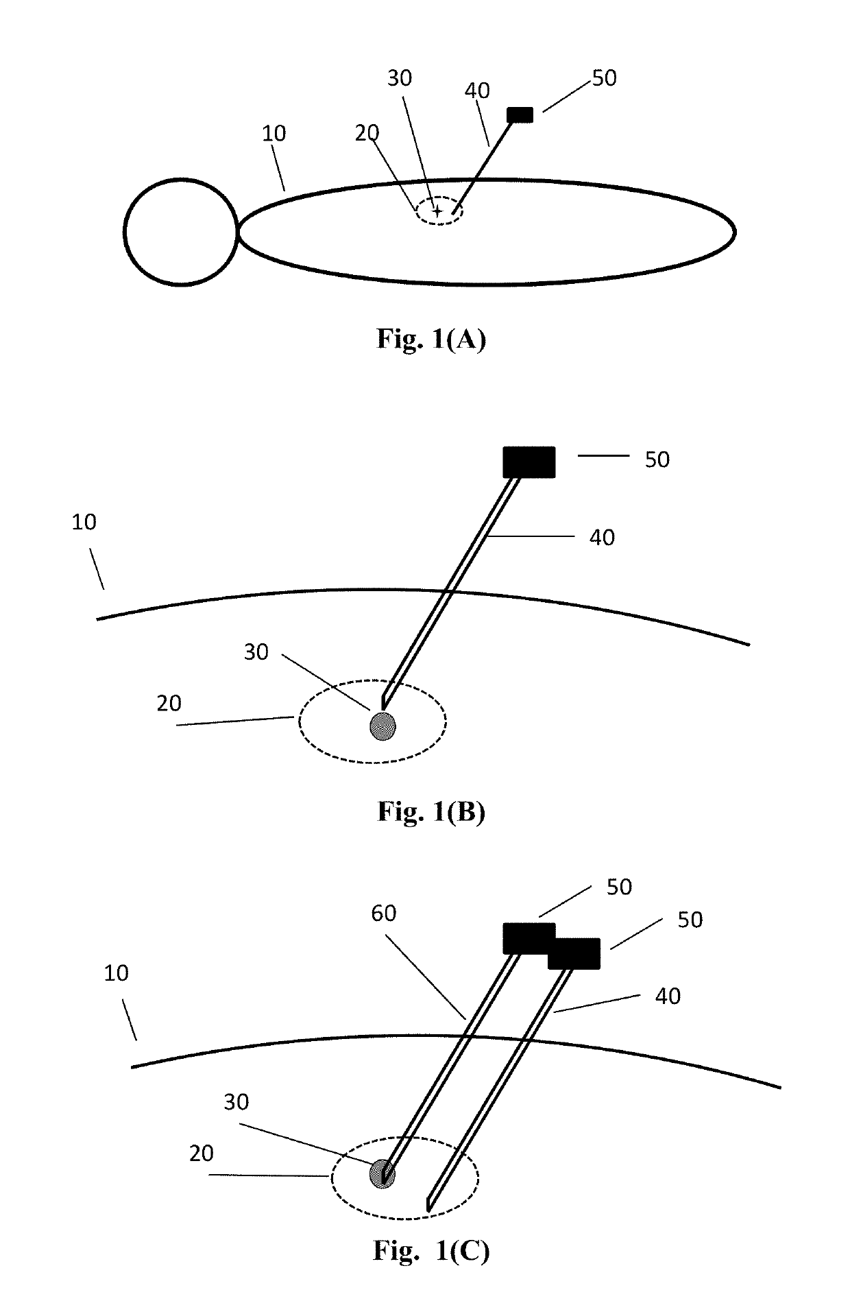
[0086]In one example, a set of cross sectional images will be taken and stored in the external computer for intervention planning. The target location and skin entry points, as well as the approach line connecting these two controlling points are marked and digitized in the computer. The physician will be instructed to align the intervention device to the planned approach line with the help of position tracking sensor element attached to the intervention device. Alternatively, the stereotactic frame will be placed near the skin entry point, and approach path is provided by aligning intervention tool holder to the desirable tool approach path. The stereotactic frame can be motorized.

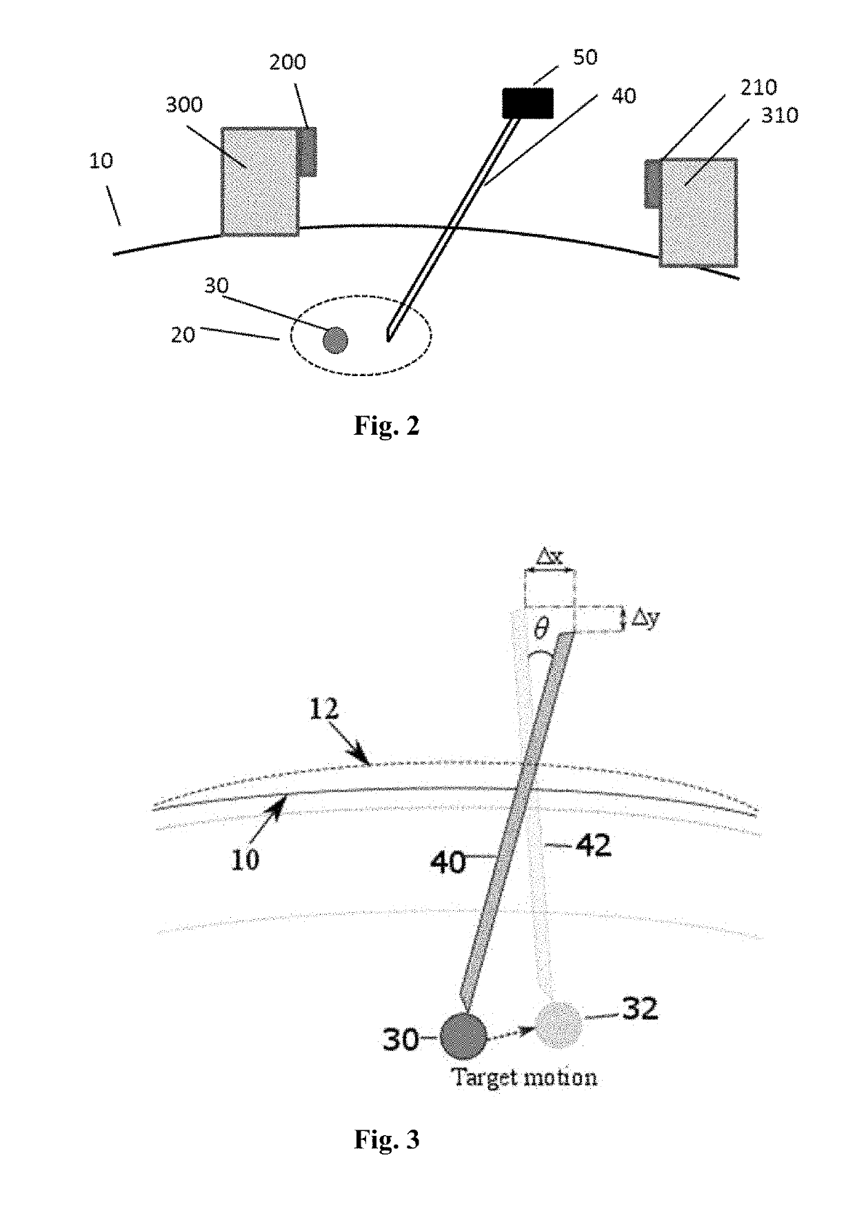
[0087]In the first instance, an in-situ sensor element is placed at the needle tip for direct motion tracking of target organ. The receiver can be placed on the abdomen. The receiver can then be registered to the cross sectional imaging system. Thus, when the needle is half inserted to an organ, in-situ s...

example 2

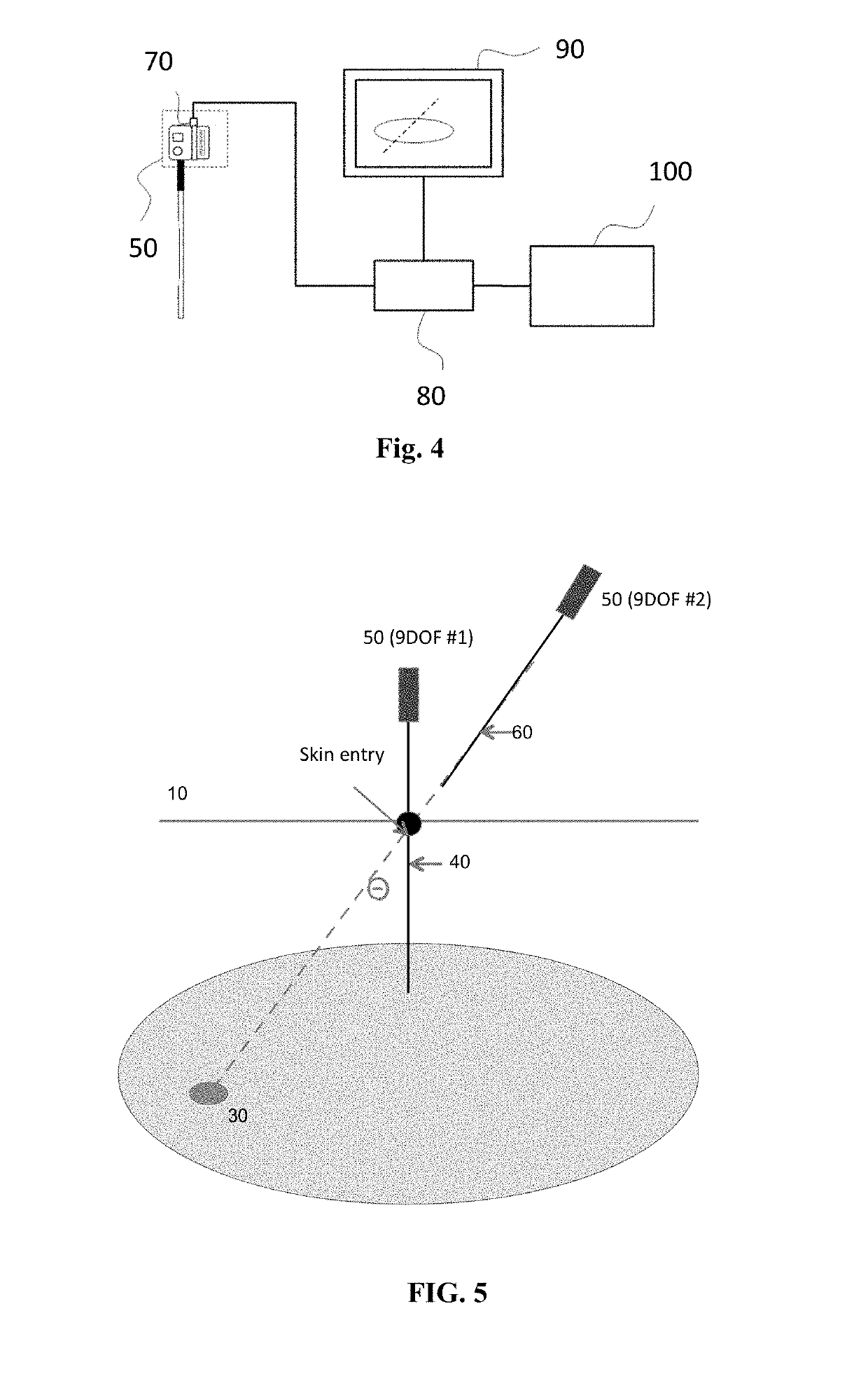
[0097]In this example, the sensor element attached to the tracking needle is a 9 degree of freedom (9DOF) sensor. In addition to the positional information, this sensor or sensors include an inertial measurement unit with a 3-axis gyroscope, a 3-axis accelerometer and a 3-axis magnetometer. The sensors, devices, and methods as described in U.S. Provisional application Ser. No. 62 / 268,378 are herein incorporated by reference in their entirety.

[0098]FIG. 5 show the 9 DOF sensor attached to the tracking needle and a second 9 DOF sensor attached to the insertion needle. In real time, continue to feedback relative angle and error from the planed path when the tracking needle is moving, or in any phase of breath holding, provide the relative angle and planed position of relative angle at the entry point 110.

[0099]FIG. 6 shows a sensor in an insertion where a robot 120, which is also registered with the sensor / tracking needle with image registration. The solid squares indicate a sectional ...

example 3

[0102]Lesion Motion in Liver. In this example, clinical data was used to measure lesion motion in liver during respiration. Liver CT images of 64 scans obtained from four patients were used to measure the target motion in liver. The scans were obtained during liver biopsy and ablations cases. The patients did not move during the procedures and the main cause of motion in the liver was respiration. A structure that resembles the lesion was localized manually in each image frame of every CT scan (FIG. 7) using a free open-source medical image computing software, 3D Slicer. The localization method was examined and reviewed by board-certified physician in general surgery with five years of experience in percutaneous ablation therapies. The results show that the target maximum absolute displacement was 12.56 mm. The main component of this motion was a superior-inferior shift 5.5±3.84 mm. The liver additionally showed motion in anterior-posterior 3.77±2.07 mm and left-right direction (3.1...


PUM


Abstract

A method and system for motion tracking of a target organ are provided. A tracking needle is partially inserted into an organ. The needle has a sensor element for obtaining continuous needle orientation information which can be used to determine organ motion due to respiration during percutaneous needle insertion.

Description

CROSS-REFERENCE TO RELATED APPLICATION(S)[0001]This application claims priority to co-pending U.S. Provisional Application Ser. No. 62 / 321,495 filed Apr. 12, 2016, and to co-pending U.S. Provisional Application Ser. No. 62 / 372,541 filed Aug. 9, 2016, the contents of each of which are incorporated herein by reference in their entirety.STATEMENT REGARDING FEDERALLY SPONSORED RESEARCH[0002]The government may own rights in this invention pursuant to National Institute of Biomedical Imaging and Bioengineering of the National Institutes of Health under award number P41EB015898.FIELD OF THE DISCLOSURE[0003]The present disclosure relates to medical devices. More particularly, the disclosure exemplifies an apparatus and method for evaluating the motion of an organ, such as during respiration.BACKGROUND INFORMATION[0004]Percutaneous needle insertions into organs such as the liver are common minimally invasive surgical procedures. Needles are often used for diagnostic and therapeutic applicati...

Claims


Application Information

Patent Timeline
IPC IPC(8): A61B34/20A61B5/00A61B5/113A61B10/02A61B18/14A61B5/06
CPCA61B34/20A61B5/7267A61B5/113A61B10/0233A61B18/1477A61B5/066A61B2017/00699A61B2090/374A61B2090/3762A61B2017/00716A61B2034/2048A61B2034/2051A61B2018/00577A61B5/6848A61B6/032A61B6/5211A61B17/3403A61B2017/00115A61B2562/0219A61B90/11
Inventor ABAYAZID, MOMENHATA, NOBUHIKOKATO, TAKAHISANINNI, BRIANTOKUDA, JUNICHISILVERMAN, STUART G.LU, ZHIMIN
Owner CANON USA
Learn More