Heart assist device

a technology of heart assist and heart valve, which is applied in the field of heart assist devices, can solve the problems of incalculable human suffering, limited clinical benefits of existing well-established treatments, and hundreds of thousands of deaths in millions of people, and achieves the effect of less invasive cannulation and better serving large numbers of patients

Active Publication Date: 2019-05-02
VADOVATIONS INC
View PDF0 Cites 14 Cited by
  • Summary
  • Abstract
  • Description
  • Claims
  • Application Information

AI Technical Summary

Benefits of technology

[0017]Thus, there remains a need for improved devices and methods that would permit less invasive cannulation of the chambers of the heart without the need for la

Problems solved by technology

Congestive heart failure is a major global public health problem that results in hundreds of thousands of deaths and incalculable human suffering in millions of people each year.
These modalities offer some symptomatic improvement and, potentially, improve survival but all are palliative treatments at best and are not curative.
Existing therapies provide limited clinical benefits for patients in advanced stages of congestive heart failure.
In fact, it is estimated that several hundred thousand patients each year with far advanced CHF experience only limited clinical benefit from existing well-established treatments, and could best be served by cardiac transplantation.
Cardiac transplantation offers significant improvement in symptoms and survival for patients with end stage heart failure but is available to only a few thousand patients each year due to the limited number of donor hearts.
Unfortunately, mechanical circulatory assistance has not developed into a commonly used therapy in the treatment of heart failure.
However, technical challenges have, thus far, precluded the development of the practical TAH needed to achieve the original vision.
Indeed, a number of effective LVADs have shown promise in clinical studies but have experienced only limited commercial success.
More specifically, two non-thoracotomy methods f

Method used


Image

  • Heart assist device
  • Heart assist device
  • Heart assist device

Examples


Embodiment Construction

[0040]Referring more specifically to the drawings, for illustrative purposes the present technology is embodied in the apparatus generally shown in FIG. 1 through FIG. 15. It will be appreciated that the apparatus may vary as to configuration and as to details of the parts, and that the method may vary as to the specific steps and sequence, without departing from the basic concepts as disclosed herein.

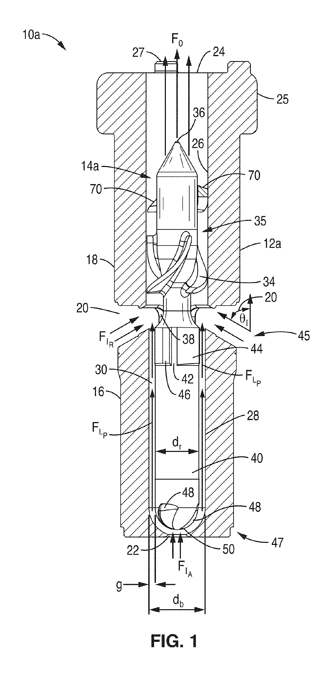
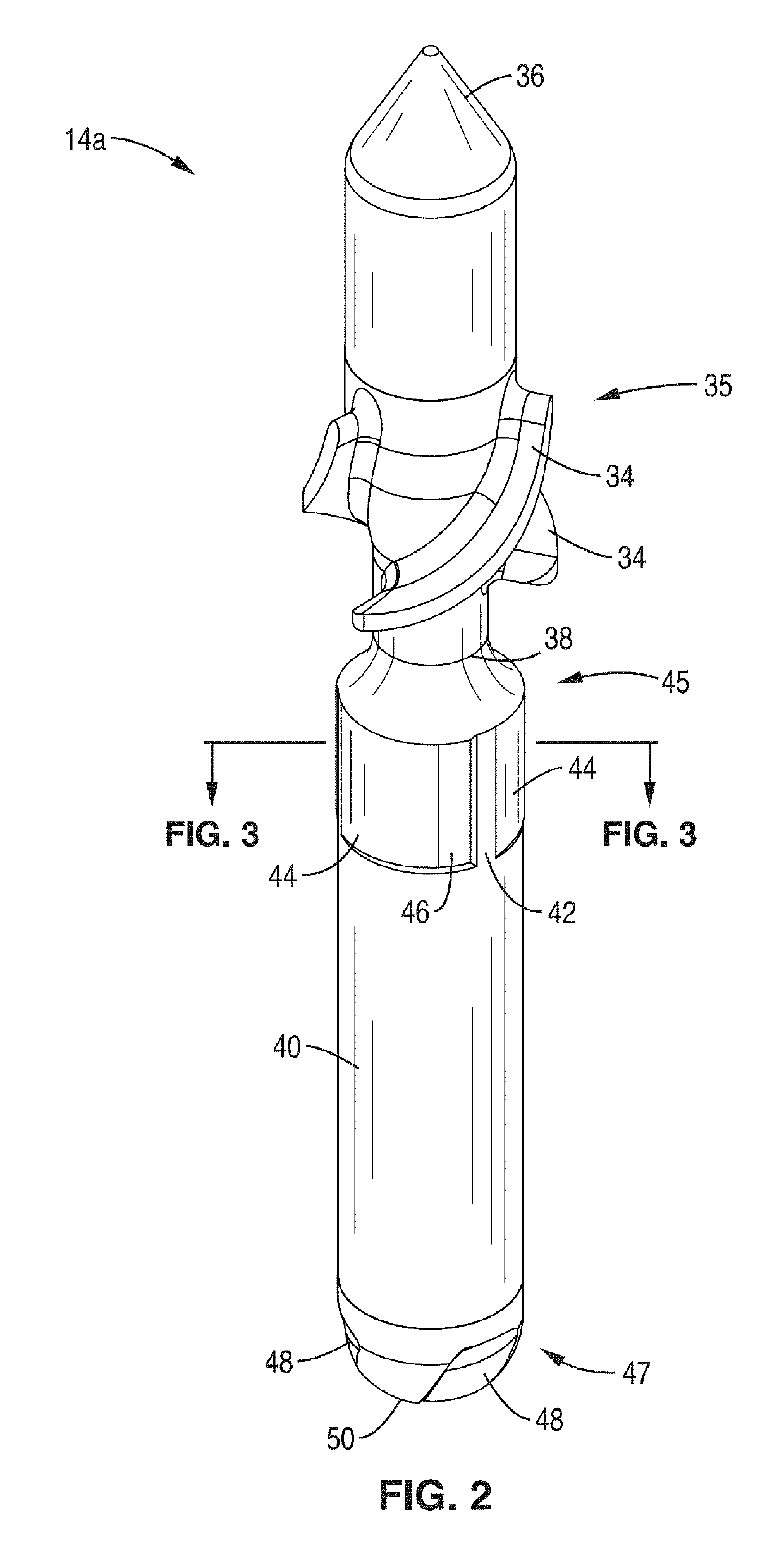
[0041]FIG. 1 through FIG. 5 show various aspects of a present embodiment minimally invasive intravascular circulatory assist pump assembly 10a that features a pump housing 12a with first and second ends 16, 18, respectively, and a rotor 14a configured to be rotatably disposed within the housing 12a. These components are configured in a particular manner relative to each other as follows.

[0042]Housing 12a includes leakage inlet 22 at first end 16, the leakage inlet 22 comprising an axially-located aperture allowing flow FIA into a cylindrical bore 28 that is disposed axially along the l...


PUM


Abstract

A heart assist device comprising a rotary pump housing having a cylindrical bore, a pumping chamber and a motor stator including an electrically conductive coil located within the housing and surrounding a portion of the cylindrical bore. A rotor has a cylindrical shaft with an impeller and one or of magnets located within the shaft that are responsive to the motor stator to drive actuation of the rotor. The housing bore is closely fitted to the outer surface of the shaft forming a hydrodynamic journal bearing with an annular clearance defining a leakage flow path. One or more of radial or axial thrust bearings may be provided to provide rotation stability to the rotor and flow within the leakage flow path. The relative orientation of positions of the inflow, outflow, and leakage flow paths may be varied within the pump, such as to accommodate different intended methods for implantation and/or use.

Description

CROSS-REFERENCE TO RELATED APPLICATIONS[0001]This application claims priority to, and is a 35 U.S.C. § 111(a) continuation of, PCT international application number PCT / US2016 / 030445 filed on May 2, 2016, incorporated herein by reference in its entirety.[0002]The above-referenced PCT international application was published as PCT International Publication No. WO 2017 / 192119 on Nov. 9, 2017, which publication is incorporated herein by reference in its entirety.NOTICE OF MATERIAL SUBJECT TO COPYRIGHT PROTECTION[0003]A portion of the material in this patent document is subject to copyright protection under the copyright laws of the United States and of other countries. The owner of the copyright rights has no objection to the facsimile reproduction by anyone of the patent document or the patent disclosure, as it appears in the United States Patent and Trademark Office publicly available file or records, but otherwise reserves all copyright rights whatsoever. The copyright owner does not...

Claims


Application Information

Patent Timeline
IPC IPC(8): A61M1/12A61M1/10
CPCA61M1/122A61M1/1017A61M1/1031A61M1/125A61M1/127A61M60/824A61M60/422A61M60/13A61M60/237A61M60/857A61M60/88A61M60/416A61M60/585A61M60/148
Inventor STANFIELD, J. RYANVLADOVICH, MICHAEL
Owner VADOVATIONS INC
Why Eureka
Try Eureka