Liquid crystal display device
a liquid crystal display and display device technology, applied in the field of liquid crystal display devices, can solve the problems of irregularities that are more likely to occur on the substrate surface of the liquid crystal display device, and portions near irregularities may not be properly rubbed by the rubbing method, so as to suppress flicker and image sticking caused by long-term us
- Summary
- Abstract
- Description
- Claims
- Application Information
AI Technical Summary
Benefits of technology
Problems solved by technology
Method used
Image
Examples
embodiment 1
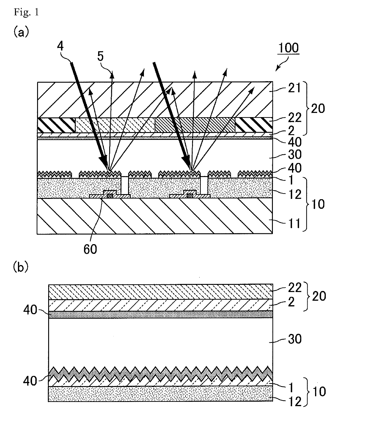
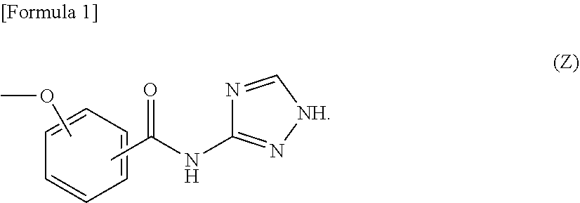
[0039]FIG. 1 is a view relating to a reflective liquid crystal display device of Embodiment 1, in which (a) is a schematic cross-sectional view of the reflective liquid crystal display device, and (b) is a schematic cross-sectional view enlarging (a). As shown in FIG. 1, a reflective liquid crystal display device 100 of the present embodiment sequentially has a first substrate 10, a liquid crystal layer 30, and a second substrate 20, and has an alignment film 40 on the liquid crystal layer 30 side of the first substrate 10 and the second substrate 20. The alignment film 40 contains a polymer having a salicylic acid derivative functional group in the side chain, and the salicylic acid derivative functional group has a structure represented by the following formula (Z). The “polymer having a salicylic acid derivative functional group in the side chain” herein is also referred to as a “polymer”.
[0040]The first substrate 10 in the reflective liquid crystal display device 100 has a thin-...
embodiment 2
[0125]A liquid crystal display device of Embodiment 2 has the same configuration as the reflective liquid crystal display device of Embodiment 1 except that the structure of the liquid crystal display device is changed to a transflective type. Thus, in the present embodiment, features peculiar to this embodiment will be described, and description overlapping with Embodiment 1 will be omitted as appropriate.
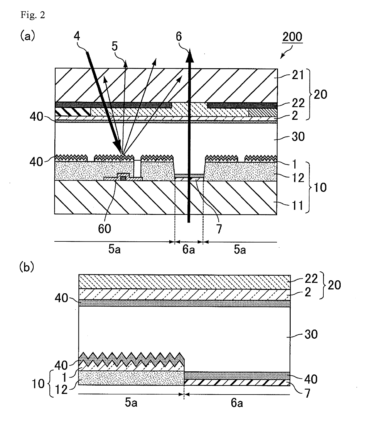
[0126]FIG. 2 is a view relating to a transflective liquid crystal display device of Embodiment 2, in which (a) is a schematic cross-sectional view of the transflective liquid crystal display device, and (b) is a schematic cross-sectional view enlarging (a). A transflective liquid crystal display device 200 of Embodiment 2 has a light reflection portion 5a having the same configuration as the reflective liquid crystal device 100 of Embodiment 1 and a light transmission portion 6a which transmits light from backlight illumination and displays an image. In the light transmission port...
examples 2-1 to 2-5
[0151]The symbol m of the polymer shown in the above formula (P1-1) was fixed to 0.2, n was changed to 1, 2, 3, 4 and 5, and polyamic acids 2-1, 2-2, 2-3, 2-4 and 2-5 were synthesized.
[0152]Reflective liquid crystal display devices of Examples 2-1 to 2-5 were produced in the same manner as in Example 1-1 except that the polyamic acid 1-1 in Example 1-1 was changed to the polyamic acids 2-1 to 2-5.
[0153]Regarding the reflective liquid crystal display devices of Examples 2-1 to 2-5, an energization test was conducted in the same manner as in Example 1-1 and the like. The obtained results are shown in Table 2 below.
TABLE 2Polyamic acidcontained inInitial (0 hour)After 100 hoursalignment filmVHR(%)rDC(V)VHR(%)rDC(V)Example 2-12-1n = 199.50.0298.30.05Example 2-22-2n = 299.50.0298.10.06Example 2-32-3n = 399.50.0398.50.05Example 2-42-4n = 499.50.0398.50.05Example 2-52-5n = 599.50.0298.40.04
[0154]As shown in Table 2, when n of R1 in the above formula (P1-1) was changed from 1 to 5 and a dis...
PUM
| Property | Measurement | Unit |
|---|---|---|
| structure | aaaaa | aaaaa |
| dielectric constant | aaaaa | aaaaa |
| voltage | aaaaa | aaaaa |
Abstract
Description
Claims
Application Information
 - R&D
- Intellectual Property
- Life Sciences
- Materials
- Tech Scout
- Unparalleled Data Quality
- Higher Quality Content
- 60% Fewer Hallucinations
Browse by: Latest US Patents, China's latest patents, Technical Efficacy Thesaurus, Application Domain, Technology Topic, Popular Technical Reports.
© 2025 PatSnap. All rights reserved.Legal|Privacy policy|Modern Slavery Act Transparency Statement|Sitemap|About US| Contact US: help@patsnap.com


