Fuel cell system

a fuel cell and system module technology, applied in the field of fuel cell systems, can solve the problems of inability to make anodes into the reducing atmosphere, the initial heating of the system generally takes several hours, etc., and achieves the effects of reducing the volume and manufacturing cost of the system module, improving the maintenance of the fuel cell system, and improving the heat dissipation efficiency of the heat generated from the fuel cell stack

Active Publication Date: 2019-05-16
MICO POWER LTD
View PDF5 Cites 3 Cited by
  • Summary
  • Abstract
  • Description
  • Claims
  • Application Information

AI Technical Summary

Benefits of technology

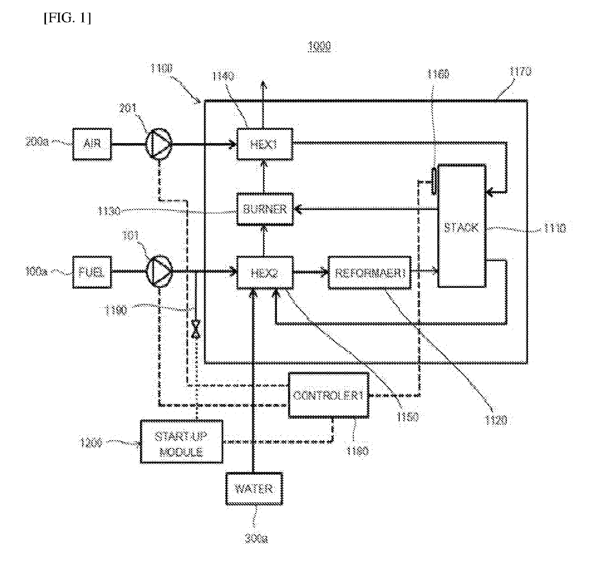
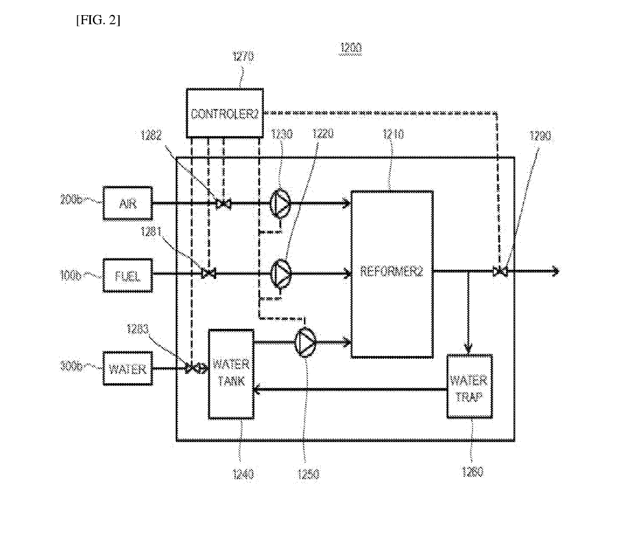
[0015]According to the fuel-cell system based on the embodiment of the present disclosure, the start-up module having the second reformer capable of reforming fuel at low temperatures allows the hydrogen-containing fuel to be supplied to the fuel-cell stack during the certain initial period of the start-up mode of the system module. Thus, the anode of the fuel-cell stack may be prevented from being oxidized during the start-up mode. In addition, configuring the start-up module independently so as to be removable from the system module may allow a volume and manufacturing cost of the system module to be reduced compared to a case of having two reformers in the system module and may allow a maintenance of the fuel-cell system to be improved. Further, the volume reduction may allow a heat dissipation efficiency of the heat generated from the fuel-cell stack to be improved.

Problems solved by technology

Such initial heating of the system generally requires several hours in consideration of thermal shock, and the like of the system.
However, when the system is consisting of a steam reformer for reforming hydrocarbon fuel via an endothermic reaction, a reforming reaction by the reformer rarely occurs in an initial low-temperature operating state, thus the anode chamber cannot be made into the reducing atmosphere.

Method used


Image

  • Fuel cell system
  • Fuel cell system
  • Fuel cell system

Examples


Embodiment Construction

[0019]Hereinafter, a stack structure for a fuel-cell according to an embodiment of the present disclosure will be described in detail with reference to the accompanying drawings. The embodiments according to this inventive concept may be variously modified and may have multiple forms. Thus, specific embodiments are illustrated in the drawings or described in detail in this specification or application. It will be understood that the description herein is not intended to limit the claims to the specific embodiments described. On the contrary, it is intended to cover alternatives, modifications, and equivalents as may be included within the spirit and scope of the present disclosure as defined by the appended claims. In the following figures, like reference numbers refer to similar elements throughout the figures. In the appended drawings, the dimensions of the structures are shown enlarged to illustrate the present disclosure for clarity.

[0020]It will be understood that, although the...


PUM

PropertyMeasurementUnit
temperatureaaaaaaaaaa
operating temperatureaaaaaaaaaa

Abstract

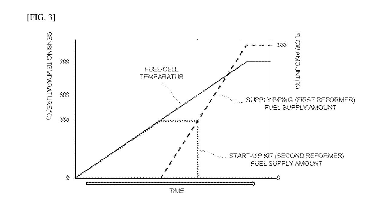
A fuel-cell system is disclosed. The fuel cell system includes: a system module having one or more fuel-cell stacks, a first reformer for converting at least some of hydrocarbon fuel into hydrogen, and supplying the hydrogen to the fuel-cell stacks, and a housing for receiving the fuel-cell stacks, and the first reformer therein; and a start-up module disposed outside the housing, and removably coupled to the system module, wherein the start-up module supplies hydrogen-containing fuel to the fuel-cell stacks until a temperature of the fuel-cell stack reaches a predetermined temperature.

Description

CROSS-REFERENCE TO RELATED APPLICATION[0001]This application claims the benefit of Korea patent application No. 10-2016-0063209 filed on May 24, 2018, the entire content of which is incorporated herein by reference for all purposes as if fully set forth herein.BACKGROUNDField of the Present Disclosure[0002]The present disclosure relates to a fuel-cell system, and more specifically to a fuel-cell system operating at high temperatures.Discussion of Related Art[0003]A fuel cell, which generates electricity via an electrochemical reaction between hydrogen and oxygen, is being actively studied because of its simple energy conversion step, and its environment-friendly characteristic of being a high efficiency and pollution-free generator.[0004]In particular, as a fuel cell operated at a high temperature of about 600° C. to 1000° C. using ceramics as an electrolyte, a solid oxide fuel-cell (SOFC) among the fuel-cells has a number of advantages. In this connection, the solid oxide fuel-cell...

Claims


Application Information

Patent Timeline
Patent Type & Authority Applications(United States)
IPC IPC(8): H01M8/04089H01M8/04302H01M8/04701H01M8/0612H01M8/124H01M8/14
CPCH01M8/04089H01M8/04302H01M8/04701H01M8/0612H01M8/124H01M8/14H01M2008/147H01M8/0618H01M8/249H01M8/04365H01M8/04373H01M2008/1293Y02E60/50H01M8/04738H01M8/0631Y02P70/50
Inventor CHOI, SONG HOYANG, BYOUNG CHANG
Owner MICO POWER LTD
Why Eureka
Try Eureka