Series clearance multi-point discharging sparking plug

a series clearance and spark plug technology, applied in the field of series clearance multi-point discharging spark plugs, can solve the problems of increasing the creep distance between the electrode and the shell, reducing the energy of the electric spark, and no enterprise and individual can provide a theoretically advanced and feasible spark plug

Inactive Publication Date: 2019-05-16
LOTUS SPARK PLUGS TECH HANGZHOU CO LTD
View PDF3 Cites 1 Cited by
  • Summary
  • Abstract
  • Description
  • Claims
  • Application Information

AI Technical Summary

Benefits of technology

[0032]Each pair of precious metal electrodes at an upper end surface of the ceramic multi-point discharging ignition table is in an upright parallel creepage discharging structure. A discharging clearance between each pair of ignition electrodes is lengthened to two to three times of the spark plug in a common structure (parameters are set according to the different discharging points), so that the flame kernel with a longitudinal section is formed into a half cylinder to rapidly diffuse (the traditional spark plug spherically diffuses due to electrode depression at a single point), because it is an unidirectional open ignition mode and not affected by the structure of spark plug in an ignition and diffusion process of the flame kernel (the traditional spark plug is affected by resistance of the side electrode and the central electrode and an electrode temperature and a structure in an early stage of the flame kernel generation), and since the spark plug is easy to suffer from the flame damping effect of the electrode temperature, a defect of ignition failure is generated at an ignition stage of a combustion theory (the duty ratio is high). An outer circle of the ceramic ignition table has an insulated prismatic structure for preventing increase of the creep distance of the electrode and the shell, thereby ensuring that the high-voltage discharge is limited to occur between each pair of electrodes. A labyrinth type isolation structure is formed at a connecting point of the central electrode, to prevent the high-voltage leakage of pulse ignition.
[0033]In this structure, the ignition energy is released in a creepage breakdown discharge form, i.e., discharge is conducted along a surface of the insulator between the central electrode and the side electrode. Since the discharging distance of the hooklike structure of the central electrode and the side electrode of the traditional spark plug is short, the arcing performance is poor. Because the size of the ignition clearance is restricted by a power voltage, the ignition clearance generally is about 0.6-1.3 mm. The short discharging distance ensures that an initial spark cannot be fully “developed” into a necessary flame center, and more electric spark heat is also absorbed and cooled by the side electrode and the central electrode, thereby reducing the energy of the electric spark and generating a hidden danger of the ignition failure. If the ignition clearance is increased, the ignition voltage needs to be increased, and due to the structure of the spark plug, internal breakdown or “fire” is easily caused by voltage increase, which is an irresolvable contradiction for the traditional spark plug. The creepage discharge occurs on an interface of a ceramic surface of the insulator between each pair of upright electrodes and the mixed gas. An electric field on the ceramic surface is distorted to increase local electric field intensity under excitation of a high-voltage electric field, causing that discharge firstly occurs locally and then promoting the further development of discharge, until the whole electrode clearance is broken down. The discharge mechanism ensures that a breakdown voltage of a creepage clearance is reduced a lot than that of same-width air clearance. If the discharge distance of the creepage clearance is longer than that of an air clearance in the same breakdown voltage, the energy of the spark can be greatly improved by the long discharging distance, because the spark discharge is composed of two parts with different energy densities, i.e., a capacitor discharge part and an inductance discharge part. The former has high energy density and high voltage, and can be discharged in a very short time; and the latter has small energy density, but plays a role in a relatively long time. From the energy distribution of the electric spark, it can be seen that the energy of the inductance part is 20-30 times of that of the capacitor pat, and plays a leading role in forming the flame kernel by heating surrounding mixed gas. The longer the duration of inductance part is, the better the success rate of ignition is. If the discharging distance is prolonged, the “flame damping effect” of the side electrode can be reduced. The electric spark burns out the oil and carbon along the surface of the insulator, thereby avoiding bridging between the electrodes, also avoiding the phenomenon of current leakage due to attaching combustion deposit between the insulator and the shell, and guaranteeing the ignition reliability in an idling condition.
[0034]The practice shows that, generally, the engine can be successively ignited only with 0.2 mJ of ignition energy in the best ignition condition, and for thicker and thinner mixed gas, the ignition energy is only 3 mJ. Due to nonuniformity of gas in the cylinder and existence of turbulence, the actual ignition energy applied to the ignition coil of the engine is generally 30-50 Mj, in order to guarantee that the engine can be successfully ignited in various working conditions. All energy is released into one point in an instant. Facts prove that, the engine efficiency cannot be increased by improving the ignition energy, but the ignition reliability is improved. The improvement of kinetic energy of the engine is determined by the combustion rate of the mixed gas, and the combustion efficiency of the mixed gas mainly depends on a concentration, a temperature and a pressure of the mixed gas, as well as a turbulence speed of the mixed gas in the cylinder, is irrelevant to the size of the ignition energy, but is directly related to an ignition position and a development speed of the flame kernel. With a feature of a high-energy ignition coil of a modern automobile ignition system, this structure is more conducive to uniform release of an ignition capacity, and the ignition energy can be uniformly distributed by a first arcing clearance and a second arcing clearance or a third clearance, so that surplus energy of the ignition coil can guarantee the success rate of ignition, and can improve the combustion rate of the engine really at ignition points in different positions.
[0035]Therefore, the series clearance multi-point discharging spark plug provided in the present invention increases temperature and pressure of mixed gas during ignition, thereby improving ignition performance, shortening complete combustion duration and improving engine power efficacy.

Problems solved by technology

So far, no enterprise and individual can provide a theoretically advanced and feasible spark plug capable of multi-point ignition at intervals in an automobile industry.
Because of a restriction of an extension structure of the central electrode, the heat radiating performance of the traditional spark plug becomes a technical obstacle of the spark plug difficult to be further improved.
Namely, the fuel is increased, and the power is reduced, with a root cause that the heat radiation of the spark plug reaches a limit value, thereby causing preignition of the engine to cause that the power is reduced.
Because of ignition structures of the central electrode and the side electrode of the traditional spark plug, a nonlinear dynamic feature is an insurmountable technical barrier.

Method used


Image

  • Series clearance multi-point discharging sparking plug
  • Series clearance multi-point discharging sparking plug
  • Series clearance multi-point discharging sparking plug

Examples


embodiment 1

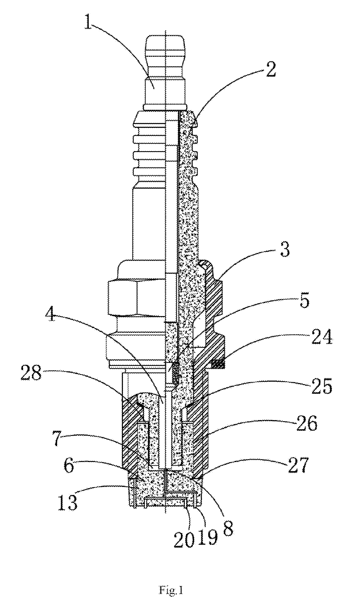
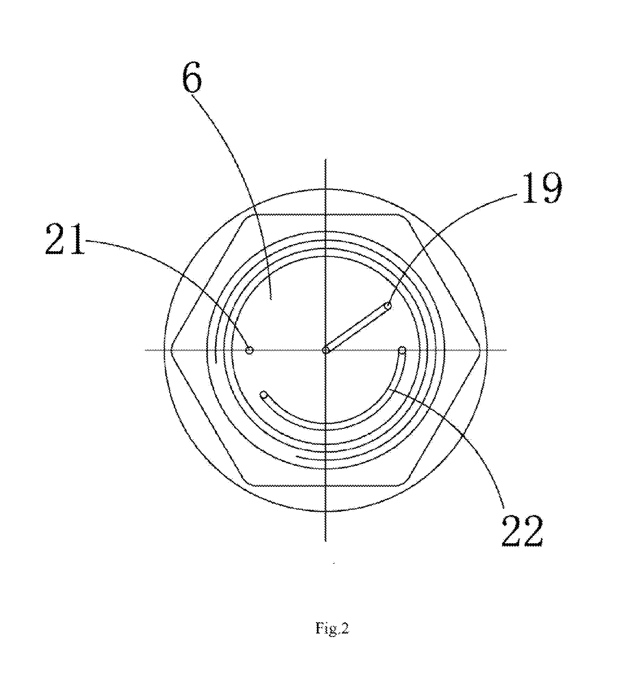
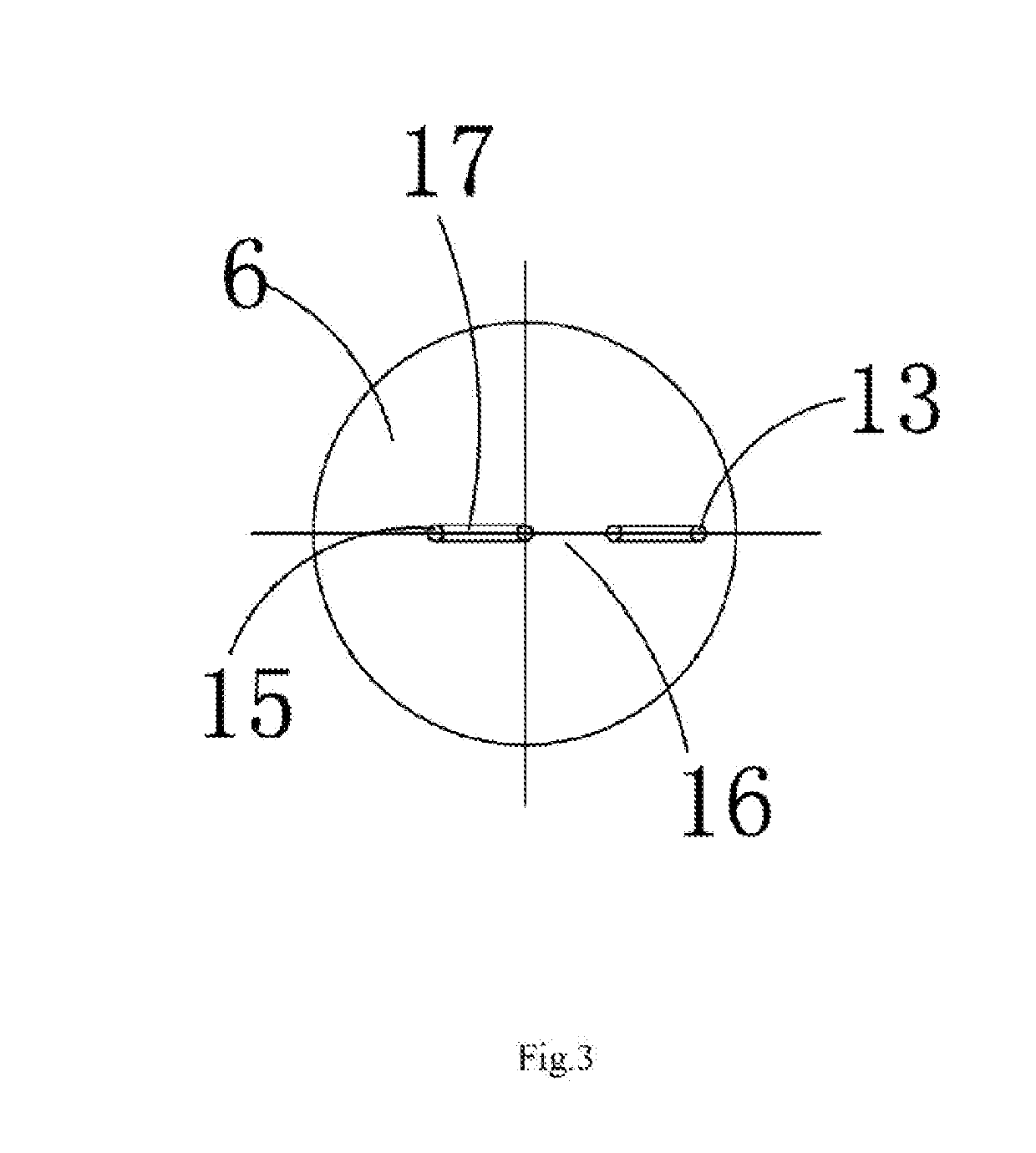
[0045]As shown in FIG. 1, FIG. 2, FIG. 3, FIG. 4, FIG. 5, FIG. 6, FIG. 7 and FIG. 8, a series clearance multi-point discharging spark plug comprises a wiring screw 1. The wiring screw 1 is arranged in an insulator 2. The insulator 2 is riveted in a shell 3. A central electrode 4 is arranged in a tip of the insulator 2. A built-in damping resistor 5 is arranged between the central electrode 4 and the wiring screw 1. A ceramic multi-point discharging ignition table 6 fitted with the insulator 2 is arranged at a bottom of the insulator 2. A cavity assembly is formed between the ceramic multi-point discharging ignition table 6 and the insulator 2. An outer wall at an upper end of the ceramic multi-point discharging ignition table 6 is fastened to the shell 3. An ignition electrode assembly is arranged at the bottom of the ceramic multi-point discharging ignition table 6. The cavity assembly comprises a positive-pole high-voltage connecting cavity 7. The bottom of the insulator 2 extends...


PUM


Abstract

The present invention relates to a series clearance multi-point discharging spark plug for a spark ignition engine, including a wiring screw. The wiring screw is arranged in an insulator. A central electrode is arranged in a tip of the insulator. A built-in damping resistor is arranged between the central electrode and the wiring screw. A ceramic multi-point discharging ignition table fitted with the insulator is arranged at a bottom of the insulator. A cavity assembly is formed between the ceramic multi-point discharging ignition table and the insulator. An outer wall at an upper end of the ceramic multi-point discharging ignition table is fastened to the shell. An ignition electrode assembly is arranged at the bottom of the ceramic multi-point discharging ignition table. The series clearance multi-point discharging spark plug increases temperature and pressure of mixed gas during ignition, thereby improving ignition performance, shortening combustion duration and improving engine performance.

Description

TECHNICAL FIELD[0001]The present invention relates to a discharging spark plug, and more specifically, to a series clearance multi-point discharging spark plug used for a spark ignition engine.BACKGROUND[0002]Currently, most of spark plugs used in a spark ignition engine fueled by gasoline, gas, alcohol and the like generally include an insulator, a shell sealing gasket, a wiring nut and the like. A central electrode is arranged in the insulator, and a built-in damping resistor is taken as a positive pole of ignition through high-temperature sealing and wiring screw connection. A side electrode made of nickel alloy material is welded on a shell, and taken as a ground pole after being installed on an engine. A hooklike arcing clearance is formed between the central electrode and the side electrode. A high-voltage ignition coil is controlled to generate high-voltage pulse electric energy under an instruction of a engine management system (ECU) at an ignition time of the engine; a high...

Claims


Application Information

Patent Timeline
Patent Type & Authority Applications(United States)
IPC IPC(8): H01T13/46
CPCH01T13/46H01T13/16H01T13/28H01T13/34
Inventor SHEN, HELINFENG, JIANGTAOYANG, SHIYANGYAN, LWEE CHEKOW, KEE FOO
Owner LOTUS SPARK PLUGS TECH HANGZHOU CO LTD
Why Eureka
Try Eureka