Electromagnetic induction device and manufacturing method therefor

a technology of electromagnetic induction device and manufacturing method, which is applied in the direction of transformer/inductance magnetic core, transformer/inductance coil/winding/connection, fixed transformer, etc., can solve the problems of energy loss and radiation damage, difficult fabrication, and difficult miniaturization of devices, so as to reduce the manufacturing difficulty, reduce the leakage of magnetic flux, and effectively reduce the effect of magnetic resistan

Inactive Publication Date: 2019-05-23
BOLYMEDIA HLDG
View PDF0 Cites 8 Cited by
  • Summary
  • Abstract
  • Description
  • Claims
  • Application Information

AI Technical Summary

Benefits of technology

[0007]With regard to the electromagnetic induction device according to the present disclosure, wrapping the coils by the magnetic cover composed of a plurality of magnetic units may, on the one hand, substantially enclose the coils to reduce magnetic flux leakage, and on the other hand, since magnetic dividing surfaces between magnetic units are disposed along a magnetic flux loop, no air gap is generated in the magnetic flux loop, thereby effectively decreasing magnetic resistance. Furthermore due to the layered structure of the magnetic c

Problems solved by technology

Such structure may lead to a large magnetic flux leakage for the transformer, causing energy loss and radiation damage.
Moreover, for the manufacture of a conventional electromagnetic induc

Method used


Image

  • Electromagnetic induction device and manufacturing method therefor
  • Electromagnetic induction device and manufacturing method therefor
  • Electromagnetic induction device and manufacturing method therefor

Examples


first embodiment

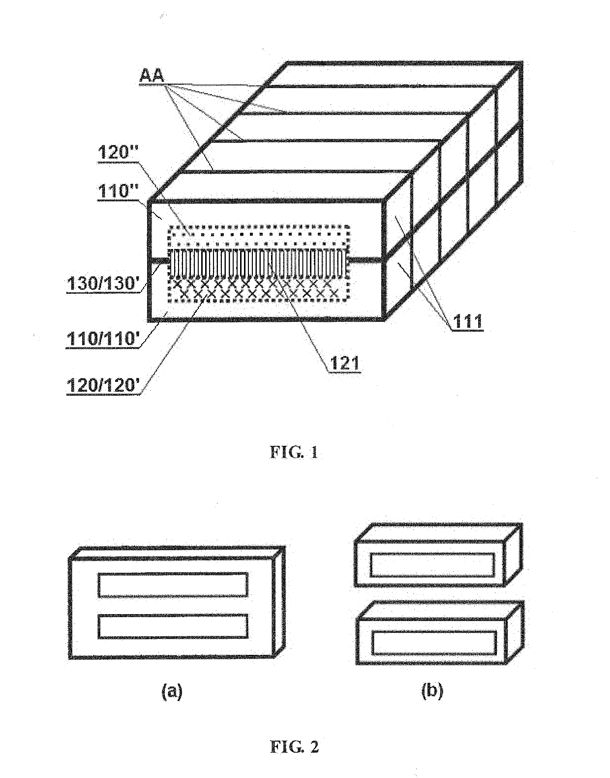
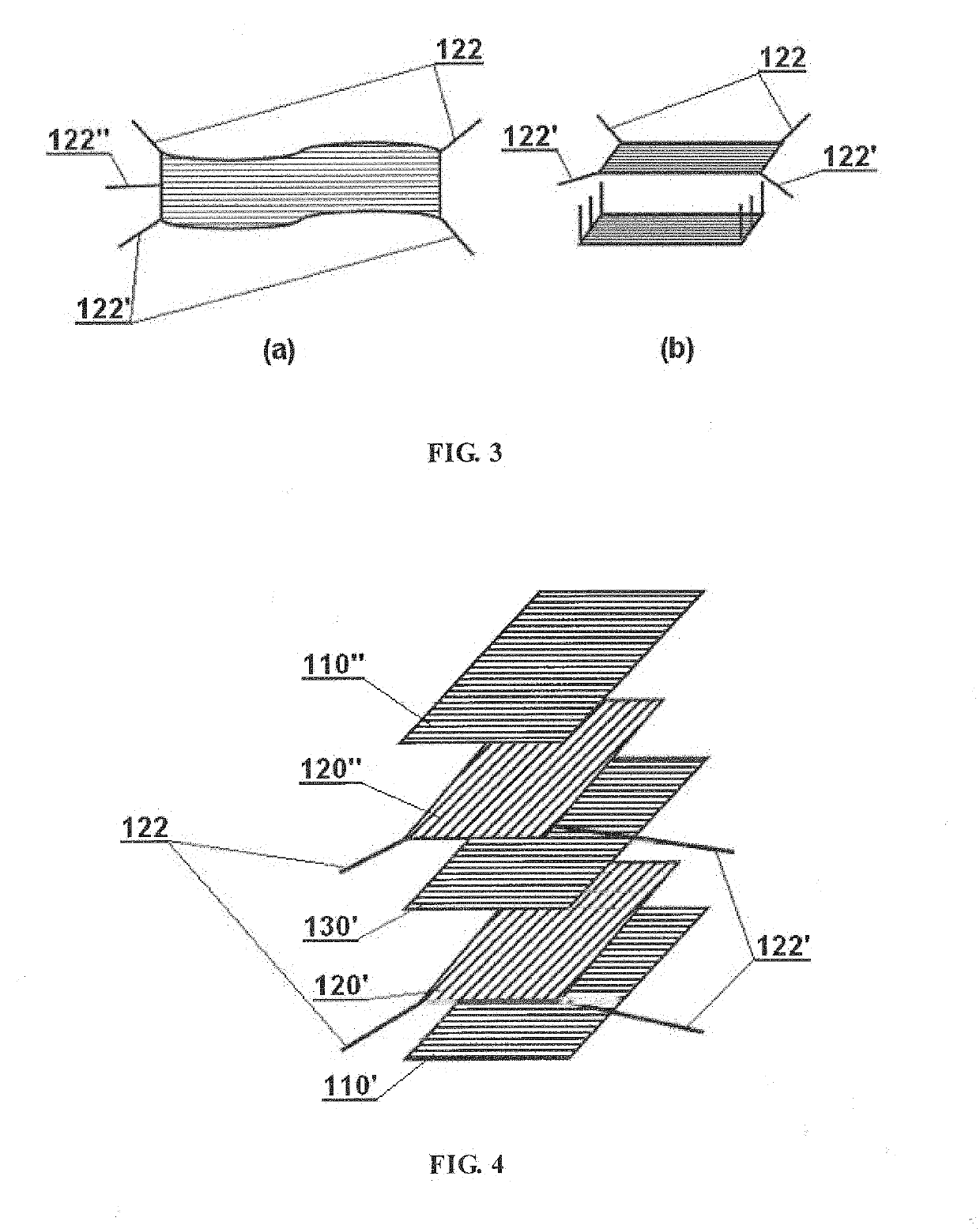
[0032]FIGS. 1 to 4 show an embodiment of electromagnetic induction device in accordance with the present disclosure. The electromagnetic induction device is a class II device and may include a magnetic cover 110, coils 120 and a magnetic core 130.

[0033]The overall structure of the device in this embodiment may include five functional layers from bottom to top successively: a first magnetic permeable layer 110′ serving as the bottom of the magnetic cover, a first electrically conductive layer 120′ serving as the lower half of the coils, a second magnetically permeable layer 130′ serving as the magnetic core, a second electrically conductive layer 120″ serving as the upper half of the coils, and a third magnetically permeable layer 110″ serving as the top of the magnetic cover. The magnetic core in this embodiment can be considered as a part of the magnetic cover.

[0034]There may be two kinds of structures to be employed when setting the magnetic dividing surface. In one kind of the st...

second embodiment

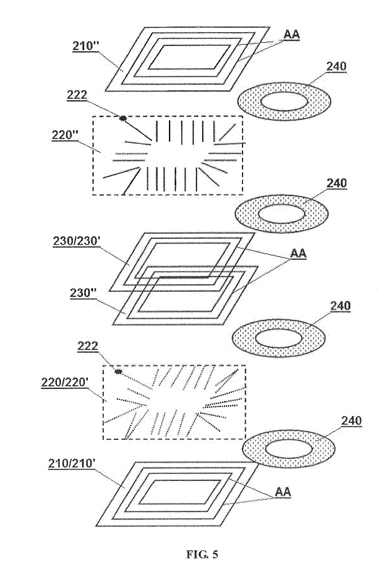
[0043]FIG. 5 and FIG. 6 show another embodiment of electromagnetic induction device in accordance with the present disclosure. The electromagnetic induction device is a class II device and may include a magnetic cover 210, coils 220 and a magnetic core 230.

[0044]The structure of this embodiment is similar to that of the first embodiment. The overall structure may include five functional layers from bottom to top successively: a first magnetic permeable layer 210′ serving as the bottom of the magnetic cover, a first electrically conductive layer 220′ serving as the lower half of the coils (the conductive lines are indicated by dotted lines), a second magnetically permeable layer 230′ serving as the magnetic core, a second electrically conductive layer 220″ serving as the upper half of the coils (the conductive lines are indicated by solid lines), and a third magnetically permeable layer 210″ serving as the top of the magnetic cover. The magnetic core and the magnetic cover in this em...

third embodiment

[0049]FIG. 7 shows still another embodiment of electromagnetic induction device in accordance with the present disclosure. The electromagnetic induction device is a class I device and may include a magnetic cover 310 and coils 320.

[0050]This embodiment which is a simple implementation of the present disclosure does not have a magnetic core, so the coils can be realized by a single electrically conductive layer, and the overall structure herein may include three functional layers, from bottom to top successively: a first magnetic permeable layer 310′ serving as the bottom of the magnetic cover, a first electrically conductive layer 320′ serving as the coils, and a third magnetically permeable layer 310″ serving as the top of the magnetic cover.

[0051]For easy to set multiple sets of coils or to increase the number of coil turns, it is preferable to add an electrically conductive layer 320″ to overlap with the first electrically conductive layer 320′. Of course, more electrically condu...


PUM


Abstract

An electromagnetic induction device, comprising a magnetic coating (110) and at least one set of coils (120). The magnetic coating (110) is formed by splicing all magnetic cells together, and is provided therein with at least one cavity. Magnetic division surfaces (AA) between each two magnetic cells are substantially arranged along a magnetic flux loop without cutting off the magnetic flux loop. The coils (120) are placed in a cavity formed by the magnetic coating (110), and the magnetic flux loop in the magnetic coating (110) is formed by the coils (120) after being energized. The overall structure of the magnetic coating (110) comprises at least two magnetically permeable layers (110′, 110″). The electromagnetic induction device, on the one hand, can be substantially closed to reduce leakage flux; on the other hand, since there is no air gap on a magnetic unit, the magnetic reluctance is effectively reduced. In addition, the magnetic coating (110) is of a layered structure so that the electromagnetic induction device can be fabricated in a superposed manner, thereby not only reducing the manufacturing difficulty, but also facilitating obtaining a high-performance flat electromagnetic induction device. Also provided is a corresponding method for manufacturing the electromagnetic induction device.

Description

TECHNICAL FIELD[0001]The present disclosure relates to electronic or electric devices, and in particular, to electromagnetic induction devices and manufacturing methods thereof.BACKGROUND OF THE INVENTION[0002]Generally, weak-current equipment (which operates in lower voltage and lower current) is referred to as an electronic device, while heavy-current equipment (which operates in higher voltage and higher current) is referred to as an electric device. Many electronic and electric devices, such as inductors, transformers and the like, operate based on electromagnetic induction effect.[0003]An electromagnetic induction device may typically include a magnetic core and a coil. A transformer is a common electromagnetic induction device. The structure of a conventional transformer is configured to wrap a magnetic core with coils. Such structure may lead to a large magnetic flux leakage for the transformer, causing energy loss and radiation damage. In order to reduce the magnetic flux le...

Claims


Application Information

Patent Timeline
IPC IPC(8): H01F27/28H01F30/06H01F27/29H01F27/24H01F27/02H01F41/04
CPCH01F27/2804H01F30/06H01F27/29H01F27/24H01F27/02H01F41/041H01F2027/2809H01F41/046H01F21/00H01F41/02
Inventor HU, XIAOPING
Owner BOLYMEDIA HLDG
Why Eureka
Try Eureka