Control device of power conversion device

a power conversion device and control device technology, applied in the direction of dynamo-electric converter control, dynamo-electric gear control, dynamo-electric brake control, etc., can solve the problems of increasing manufacturing costs, limiting the deterioration of detection accuracy of current, and complicated configuration of control devices, so as to limit the loss of synchronization, limit the loss of motor control accuracy and monitoring accuracy, and limit the loss of detection accuracy

Active Publication Date: 2019-06-20
DENSO CORP
View PDF6 Cites 1 Cited by
  • Summary
  • Abstract
  • Description
  • Claims
  • Application Information

AI Technical Summary

Benefits of technology

The present invention is for a control device that can control a motor with a certain amount of force. The device uses a special device to convert power to control the motor, and it also uses a monitoring system to keep track of the motor's movement. The invention aims to make sure that both the monitoring system and the control system are always in synch, so that the motor control and monitoring accuracy are never compromised. This means that the device can detect the electric current and the motor angle with the best possible accuracy, which is important for ensuring the motor operates in the desired way.

Problems solved by technology

The control system and the monitoring system provided as separate microcomputers may complicate the configuration of the control device and increase the manufacturing costs.
The hardware resources used in a sharing manner by the control system and the monitoring system for the acquiring the current and the angle may cause a “collision,” where the acquisition request for the current from the control system and the acquisition request for the angle from the monitoring system occur almost simultaneously and collide.
The present disclosure limits the deterioration of detection accuracy of the current and the angle in the control device to limit the loss of motor control accuracy and monitoring accuracy.

Method used


Image

  • Control device of power conversion device
  • Control device of power conversion device
  • Control device of power conversion device

Examples


Embodiment Construction

[0018]Embodiments of the present disclosure are described in the following paragraphs with reference to the drawings.

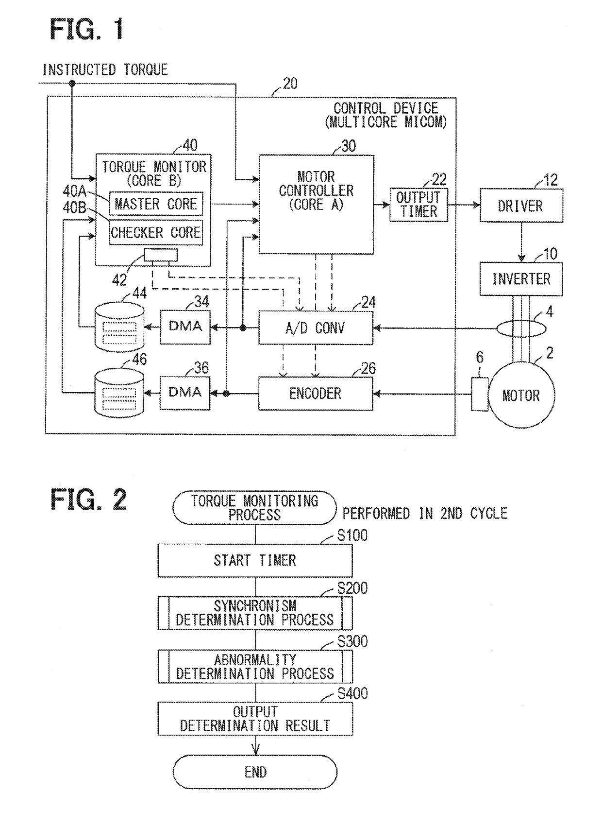
[0019]As shown in FIG. 1, a control device 20 of the present embodiment controls a motor 2. The motor 2 may be an electric traction motor in a vehicle (not shown) such as an electric vehicle or hybrid vehicle for propelling the vehicle based on an instructed torque (i.e., torque instruction) from a vehicle control device, such as the control device 20. The vehicle control device may control the travel / drive of the vehicle.

[0020]The motor 2 may be, for example, a three-phase alternating current (AC) motor that operates in conjunction with an inverter 10 that supplies an alternating electric power from a battery in the vehicle to each of the three phases of the motor 2. That is, the inverter 10 is a power conversion device for driving the motor 2.

[0021]A current sensor 4 may be connected to the motor 2 for detecting a motor current flowing from the inverter 10 to the wi...


PUM


Abstract

A control device of a power conversion device for driving a motor includes a current detector and an angle detector. The control devices also includes a motor controller that acquires an electric current and an angle from the respective detectors in a first cycle and drives the motor via the power conversion device, and a toque monitor that acquires the electric current and the angle from the respective detectors in a second cycle and estimates an output torque for determining abnormalities in the motor control. The control device prioritizes acquisition requests for the current and angle from the motor controller and the torque monitor. The torque monitor acquires the current and angle at least twice in the second cycle to acquire a current and angle that are detected at the same time by the detectors.

Description

CROSS REFERENCE TO RELATED APPLICATION[0001]The present application is based on and claims the benefit of priority of Japanese Patent Application No. 2017-243816, filed on Dec. 20, 2017, the disclosure of which is incorporated herein by reference.TECHNICAL FIELD[0002]The present disclosure generally relates to a control device that drives a motor with a torque instruction via a power conversion device that converts externally supplied electric power to electric power for driving the motor.BACKGROUND INFORMATION[0003]In vehicles that use an electric drive / traction motor as a propulsion source, such as electric vehicles and hybrid vehicles, the motor is driven so that the output torque of the motor matches a torque instruction from a vehicle control device. The torque instruction from the vehicle control device may be an instructed torque value to be output by the motor.[0004]The power conversion device for driving a motor in such a vehicle is generally accompanied by a control device...

Claims


Application Information

Patent Timeline
IPC IPC(8): H02P21/20H02P21/14H02P21/18H02P21/22
CPCH02P21/20H02P21/14H02P21/18H02P21/22H02P27/08H02P29/024
Inventor KUROKAWA, SHO
Owner DENSO CORP
Why Eureka
Try Eureka