Electro-optical device and electronic apparatus
- Summary
- Abstract
- Description
- Claims
- Application Information
AI Technical Summary
Benefits of technology
Problems solved by technology
Method used
Image
Examples
first exemplary embodiment
Electro-Optical Device
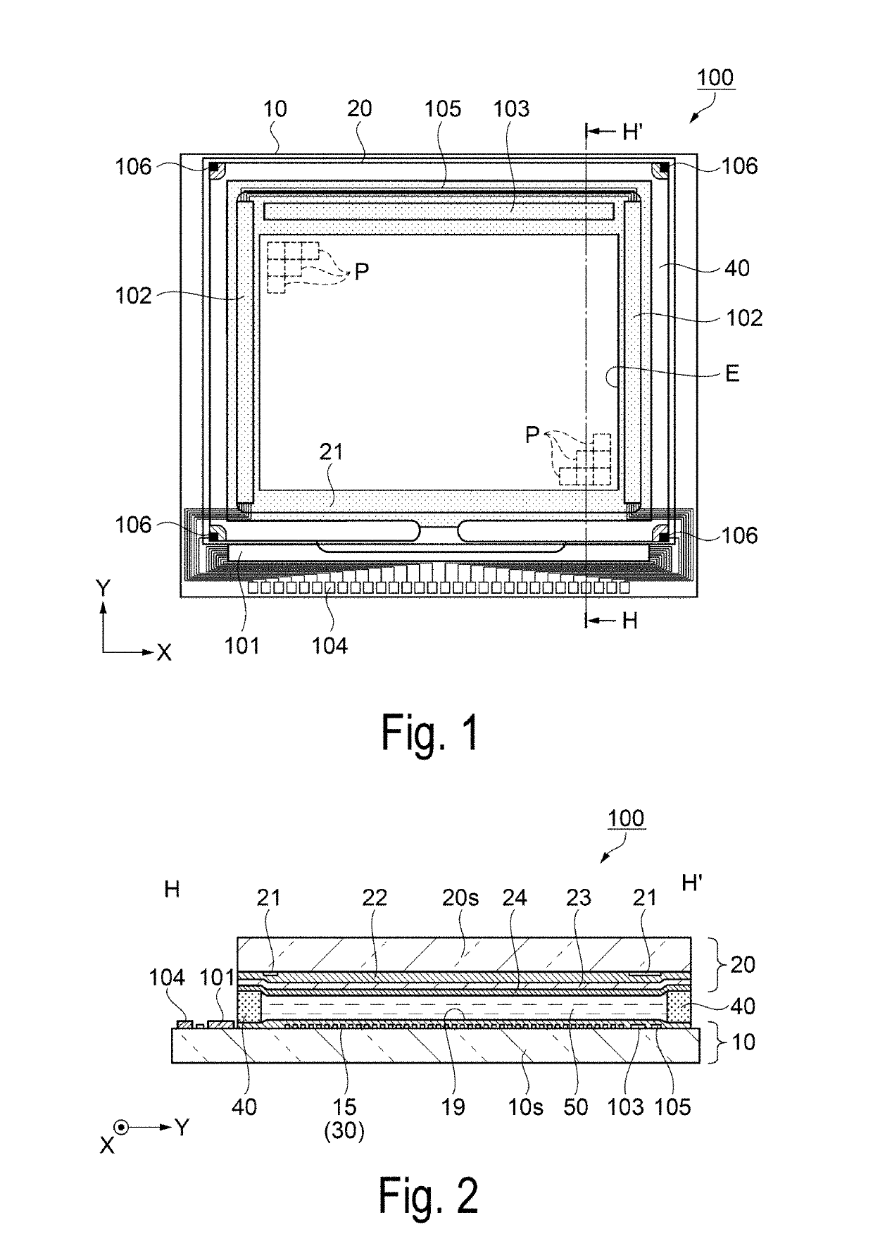
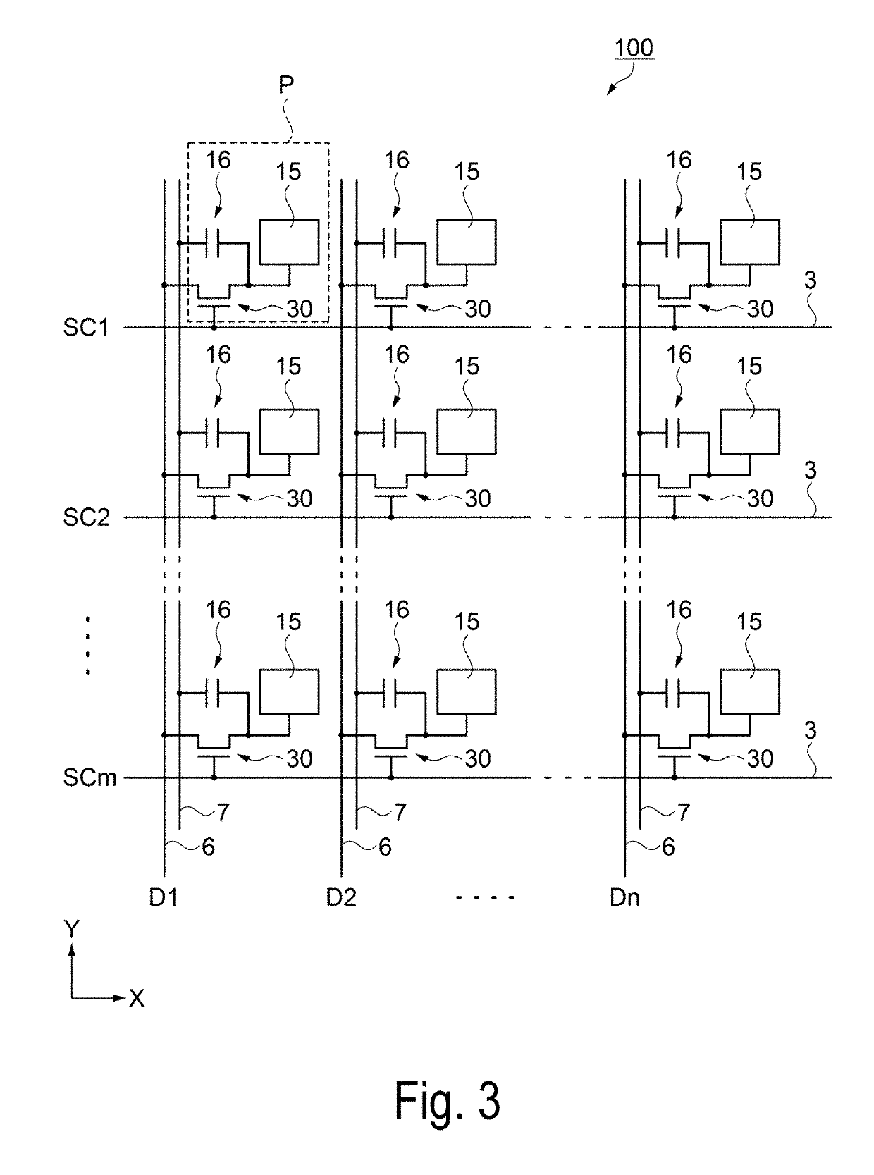
[0066]First, a configuration of a liquid crystal device as an electro-optical device according to a first exemplary embodiment will be described with reference to FIGS. 1 to 3. FIG. 1 is a schematic plan view illustrating a configuration of a liquid crystal device as an electro-optical device according to the first exemplary embodiment, FIG. 2 is a schematic cross-sectional view taken along line H-H′ of the liquid crystal device illustrated in FIG. 1, and FIG. 3 is an equivalent circuit diagram illustrating an electrical configuration of the liquid crystal device according to the first exemplary embodiment.
[0067]As illustrated in FIG. 1 and FIG. 2, a liquid crystal device 100 of the first exemplary embodiment includes an element substrate 10 and a counter substrate 20 disposed to face each other, and a liquid crystal layer 50 interposed between a pair of these substrates. For example, a quartz substrate or a glass substrate having a translucent property is used...
second exemplary embodiment
Electro-Optical Device
[0151]Next, an electro-optical device of the second exemplary embodiment will be described by exemplifying a liquid crystal device as with the first exemplary embodiment. The liquid crystal device as the electro-optical device of the second exemplary embodiment includes a liquid crystal layer interposed between an element substrate and a counter substrate, and is different from the first exemplary embodiment in disposition of a scanning line and a holding capacitor between a base substrate 10s and a TFT 30 in the element substrate and a configuration related to each of the scanning line and the holding capacitor. Accordingly, the same configurations as the configurations in the liquid crystal device 100 of the first exemplary embodiment are denoted by the same reference signs, and detailed description of the same configurations will be omitted.
[0152]FIG. 22 is a schematic plan view illustrating disposition of the TFT, wiring, and the like at an intersection of ...
third exemplary embodiment
Electronic Apparatus
[0204]Next, a projection-type display apparatus will be described with reference to FIG. 28 as an example of an electronic apparatus to which the liquid crystal device according to each of the above-described embodiments is applied. FIG. 28 is a schematic view illustrating a configuration of the projection-type display apparatus as the electronic apparatus.
[0205]As illustrated in FIG. 28, a projection-type display apparatus 1000 as an electronic apparatus according to a third exemplary embodiment includes a polarized light illumination apparatus 1100 disposed along a system optical axis L, and two dichroic mirrors 1104 and 1105 as light separation elements. In addition, the projection-type display apparatus 1000 includes three reflection mirrors 1106, 1107 and 1108 and five relay lenses 1201, 1202, 1203, 1204, and 1205. Further, the projection-type display apparatus 1000 includes liquid crystal light bulbs 1210, 1220, and 1230 of a transmissive type as three ligh...
PUM
 Abstract
Description
Claims
Application Information
 - R&D
- Intellectual Property
- Life Sciences
- Materials
- Tech Scout
- Unparalleled Data Quality
- Higher Quality Content
- 60% Fewer Hallucinations
Browse by: Latest US Patents, China's latest patents, Technical Efficacy Thesaurus, Application Domain, Technology Topic, Popular Technical Reports.
© 2025 PatSnap. All rights reserved.Legal|Privacy policy|Modern Slavery Act Transparency Statement|Sitemap|About US| Contact US: help@patsnap.com


