Retractable hollow finger for harvesting header

a hollow finger and header technology, applied in the direction of mowers, agriculture tools and machines, etc., can solve the problems of serious damage to the auger tube or the operating mechanism within the auger tube, tubular fingers tend to break at random locations along their length, and further damage to the peripheral wall and the finger drive assembly, so as to reduce the overall inertial load, and reduce the inertial load of the finger drive arrangement

a hollow finger and header technology, applied in the direction of mowers, agriculture tools and machines, etc., can solve the problems of serious damage to the auger tube or the operating mechanism within the auger tube, tubular fingers tend to break at random locations along their length, and further damage to the peripheral wall and the finger drive assembly, so as to reduce the overall inertial load, and reduce the inertial load of the finger drive arrangement

US20190200525A1Inactive Publication Date: 2019-07-04MACDON INDS

Image

  • Retractable hollow finger for harvesting header
  • Retractable hollow finger for harvesting header
  • Retractable hollow finger for harvesting header

Examples


Embodiment Construction

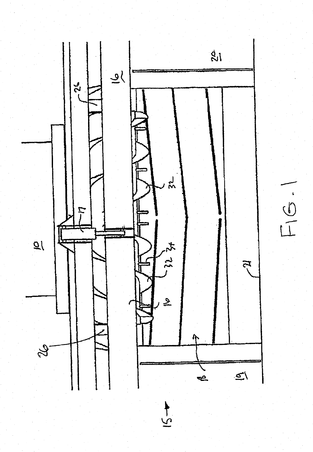
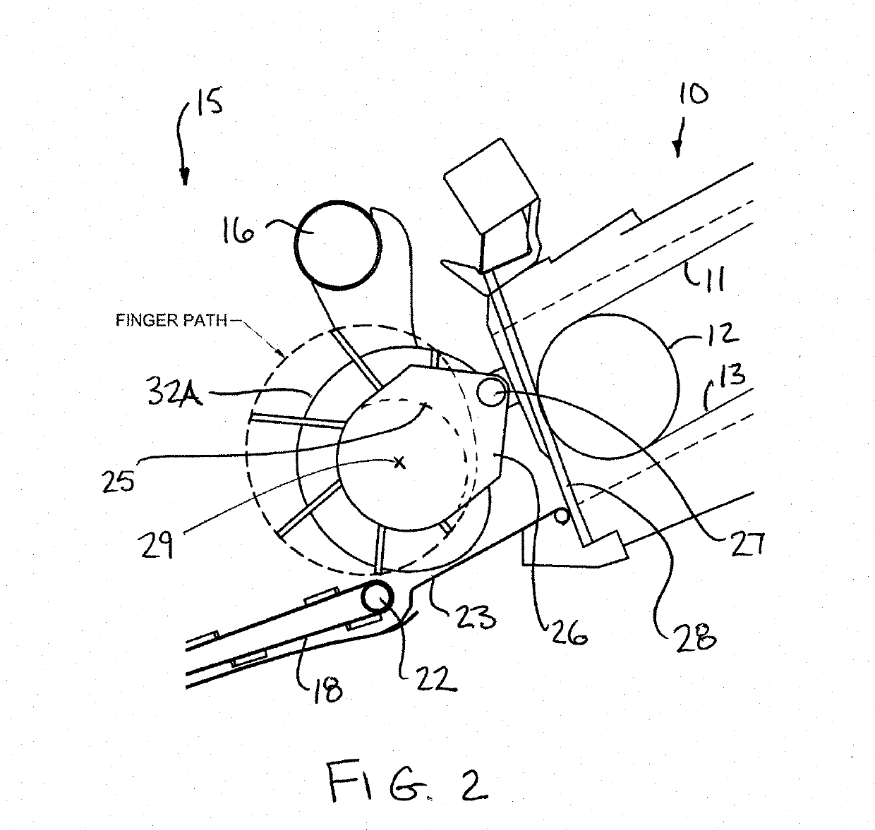
[0052]In FIGS. 1 and 2 is shown an arrangement of header and feeder house 10 for a combine harvester of the type generally shown in U.S. Pat. No. 6,675,568 issued Jan. 13, 2004 of the present assignee, the disclosure of which is incorporated herein by reference. This shows one example of an arrangement in which the invention can be used, but many other locations for the use of a feed roller of this type are well known to a person skilled in the art.

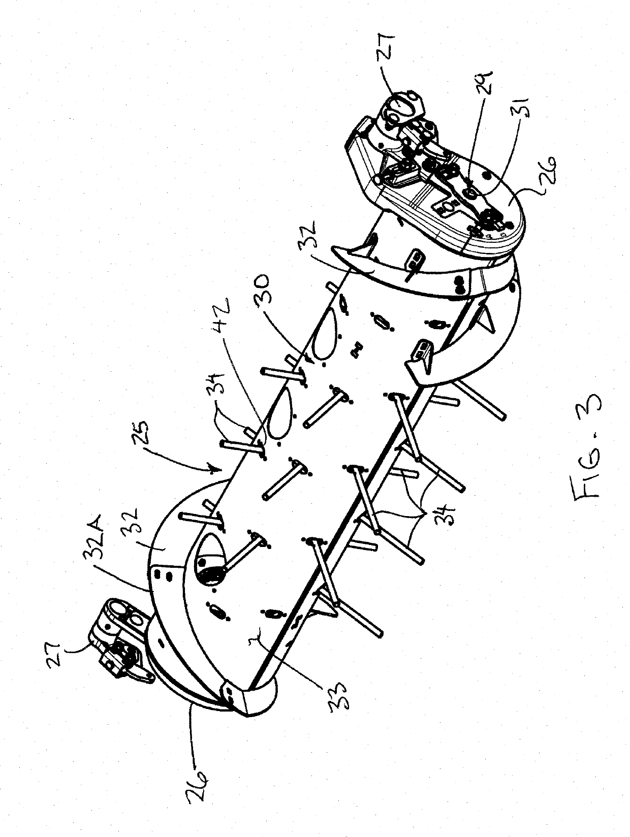
[0053]Details of the main construction of the header are omitted since these are well known to one skilled in the art and are available from the above patent document. The present arrangement is concerned primarily with the construction of the retractable fingers for use in a feed roller. Although one example of the feed roller is described herein, other feed roller arrangements may vary in accordance with the requirements of a person skilled in the art.

[0054]The arrangement as shown comprises a feeder house 10 having a feeder chain 11 mo...


PUM


Abstract

A crop feeding apparatus having a roller through which the fingers are extended and retracted, has fingers that are formed with tubular finger bodies extending between an inner end configured to be mounted on a finger drive arrangement of the crop feeding apparatus and an outer end of the finger body configured to protrude from the outer peripheral wall of the roller. A breakaway region is formed in the finger body by diametrically opposed slots which are circumferentially elongated to define a shear plane perpendicular to the long axis of the finger body. A slot axis extending between opposing ends of each slot is parallel to the axis of the crop feeding apparatus. The finger body is also hardened by heat treating, and by applying a wear resistant coating over the heat treated body.

Description

[0001]This invention relates to a feed roller of the type having generally radially extending fingers which move relative to the roller axis so that their length extending from the roller surface changes around the roller axis for engaging into and for releasing the crop.BACKGROUND OF THE INVENTION[0002]Feed rollers are commonly used in crop harvesting machines for guiding the crop from a position in front of the roller to a position rearwardly of the roller. Such rollers are used in many different locations in crop feeding systems and the arrangement described herein is not limited to any particular location of such a crop feeding roller.[0003]However, one primary use of such rollers is in that of guiding the crop from a harvesting header into the feeder house of a combine harvester. Such headers can be of the type which simply provide a cutter bar across the front of the header using any suitable cutting technique behind which is located the guide roller which includes an auger fl...

Claims


Application Information

Patent Timeline
04 Jul 2019
Publication
US20190200525A1
IPC
A01D61/00; A01D41/12; A01D57/01
CPC
A01D61/006; A01D61/008; A01D41/12; A01D57/01; A01D57/02; A01D41/14
Inventors
MACMILLAN, MYLES BRUCE; ENNS, JOHN EDWARD