
Ferromagnetic Resonance (FMR) Electrical Testing Apparatus for Spintronic Devices

a testing apparatus and magnetic resonance technology, applied in the direction of instruments, material analysis, measurement using electron paramagnetic resonance, etc., can solve the problem of preventing wide acceptance of fmr, and achieve the effect of reliable scanning fmr measurement system, convenient implementation, and convenient configuration

Active Publication Date: 2019-07-25
TAIWAN SEMICON MFG CO LTD
View PDF13 Cites 3 Cited by
  • Summary
  • Abstract
  • Description
  • Claims
  • Application Information

AI Technical Summary

Benefits of technology

This patent describes a new system for measuring magnetic structures on wafers without needing to cut them open. The system is fully automated and uses commercially available components. It also ensures that the magnetic field is applied to the wafer in a more uniform way, which improves the accuracy of the data collected during the measurements. The system has been designed to be easily implemented in both engineering and production environments. Overall, this new system offers improved accuracy and efficiency for the measurement of magnetic structures on wafers.

Problems solved by technology

Since conventional FMR techniques are destructive, time consuming, and limited to measuring large structures having a cross-sectional size substantially greater than 1 mm, they are undesirable to an extent that prevents wide acceptance of FMR as a characterization tool in the magnetic data storage industry.

Method used


Image

  • Ferromagnetic Resonance (FMR) Electrical Testing Apparatus for Spintronic Devices
  • Ferromagnetic Resonance (FMR) Electrical Testing Apparatus for Spintronic Devices
  • Ferromagnetic Resonance (FMR) Electrical Testing Apparatus for Spintronic Devices

Examples


first embodiment

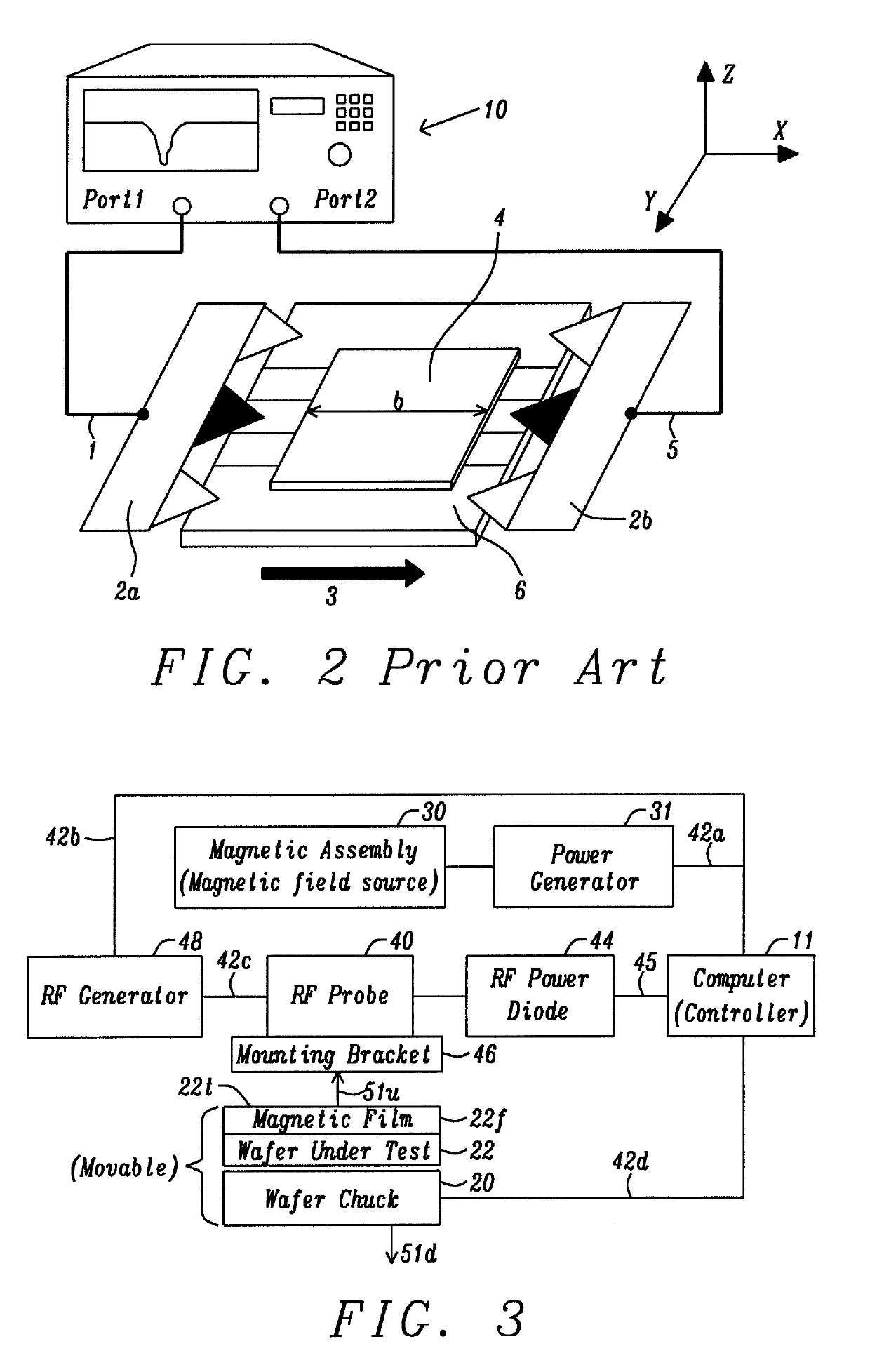
[0043]The controller 11 has an electrical connection 42b to a RF generator 48 that provides a plurality of microwave frequencies through link 42c to a first RF connector (not shown) on RF probe 40. In some embodiments, the RF generator produces a first microwave frequency (f1) in the range of 1 to 20 GHz. However, the present disclosure anticipates inserting a frequency multiplier module (not shown) between the RF generator and RF probe that adjusts f1 to a second RF frequency (f2) where f2>f1. For example, when f1=20 GHz, the frequency multiplier module may be an active frequency doubler that adjusts f1 to f2 where f2=40 GHz. RF frequencies below 1 GHz are not practical for the purpose of inducing a FMR condition in the magnetic film.

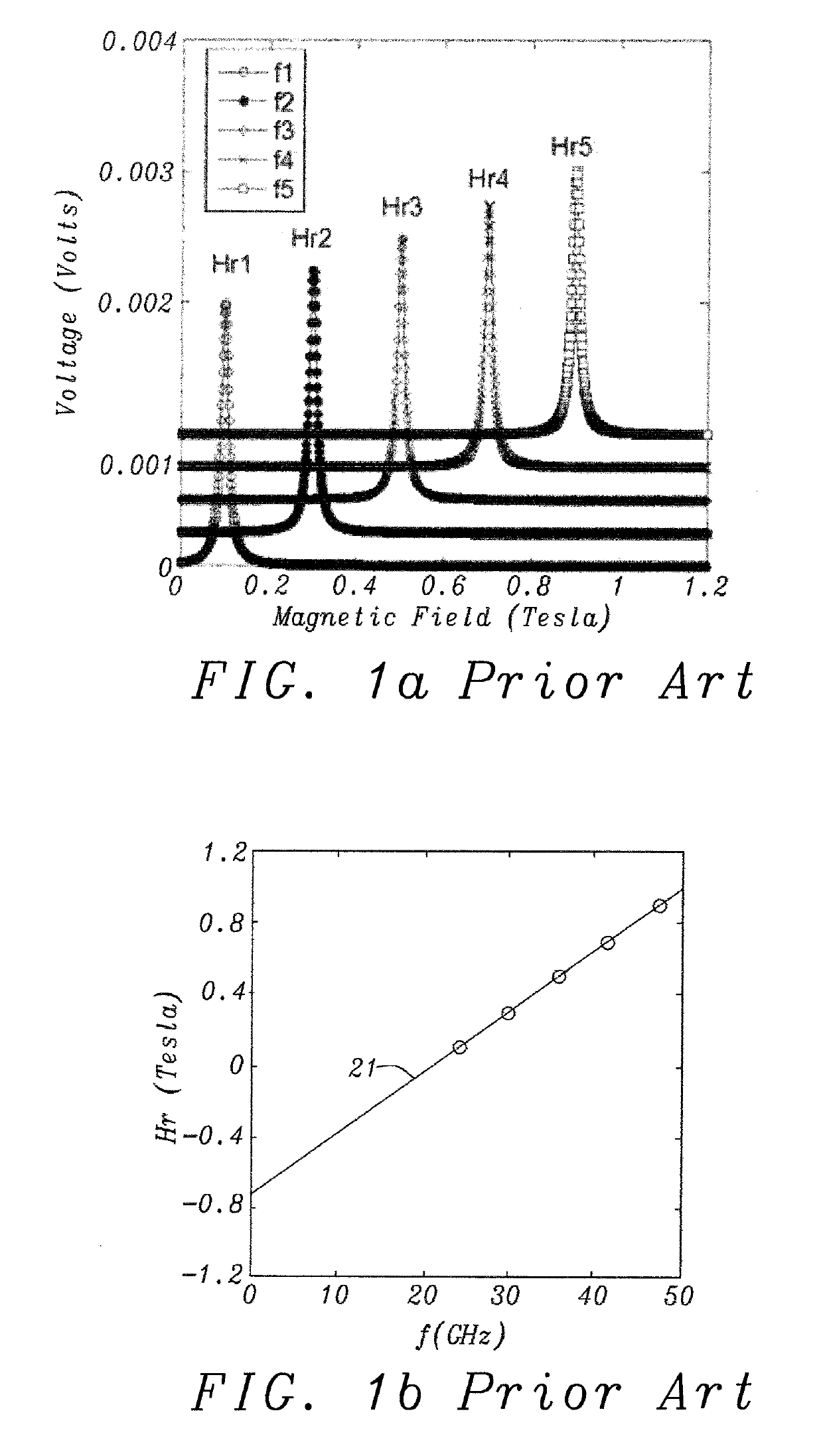
[0044]In a preferred operating mode for a FMR measurement, the applied magnetic field is varied (swept from a minimum to a maximum value) at a constant microwave frequency. The FMR measurement is preferably repeated by sweeping the magnetic field succ...

second embodiment

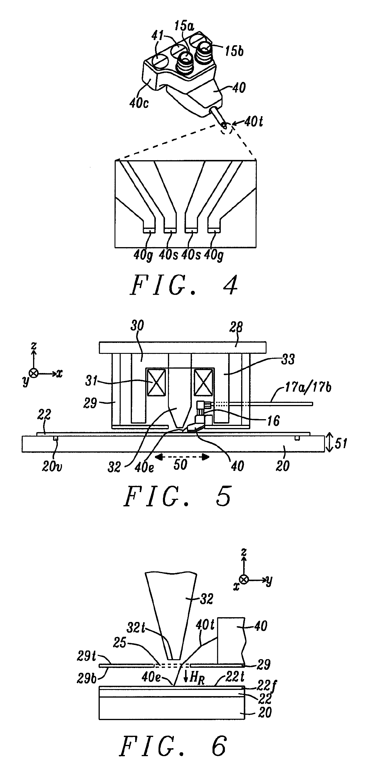
[0049]Referring to FIG. 7, the scanning FMR measurement system of the present disclosure is shown that retains all of the features of the previous embodiment except the magnetic assembly comprises two magnetic poles 32a, 32b that are each surrounded by Cu coils 31, and are positioned on either side of the RF probe tip 40e, and proximate to the WUT 22 but not touching the magnetic film (not shown). Here a first pole may apply the in-plane magnetic field HR while a second pole may serve as the return pole. Thus, the pole configuration produces a magnetic field HR in the plane of the magnetic film proximate to the (xn, yn) coordinate where the RF probe tip contacts the top surface thereof. Applied RF frequencies during FMR measurements for this magnetic assembly configuration may be in the range of 0.01 to 100 GHz.

[0050]Referring to FIG. 8, a schematic drawing of a scanning FMR measurement system configured for a RF signal transmission mode is depicted according to a first embodiment o...


PUM


Abstract

A scanning ferromagnetic resonance (FMR) measurement system is disclosed with a radio frequency (RF) probe and one or two magnetic poles mounted on a holder plate and enable a perpendicular-to-plane or in-plane magnetic field, respectively, at test locations. While the RF probe tip contacts a magnetic film on a whole wafer under test (WUT), a plurality of microwave frequencies (fR) is sequentially transmitted through the probe tip. Simultaneously, a magnetic field (HR) is applied to the contacted region thereby causing a FMR condition in the magnetic film for each pair of (HR, fR) values. RF output signals are transmitted through or reflected from the magnetic film to a RF diode and converted to voltage signals which a controller uses to determine effective anisotropy field, linewidth, damping coefficient, and / or inhomogeneous broadening for a sub-mm area. The WUT is moved to preprogrammed locations to enable multiple FMR measurements at each test location.

Description

RELATED PATENT APPLICATION[0001]This application is related to Docket # HT16-012, Ser. No. 15 / 463,074, filing date Mar. 3, 2017; which is assigned to a common assignee and is herein incorporated by reference in its entirety.TECHNICAL FIELD[0002]The present disclosure relates to a system for measuring magnetic properties in magnetic films and structures in regions as small as sub-millimeter in diameter, and a method for doing the same, and in particular, to a magnetic assembly and RF probe that are mounted on a platform and installed in an electrical probe station to enable fully automated FMR testing of films and structures across entire wafers without a need to cut the wafers in engineering or manufacturing environments.BACKGROUND[0003]Magnetic thin films and multilayers play a key role in various types of magnetic storage devices such as a magnetic hard disk (HDD) drive, Magnetic Random Access Memory (MRAM), spin torque oscillator (STO), and magnetic domain wall devices. In order ...

Claims


Application Information

Patent Timeline
IPC IPC(8): G01R33/24G01N24/00
CPCG01R33/24G01N24/00G01N24/10G01R33/60
Inventor JAN, GUENOLELE, SONTHOMAS, LUCGUISAN, SANTIAGO SERRANO
Owner TAIWAN SEMICON MFG CO LTD
Features
  • Generate Ideas
  • Intellectual Property
  • Life Sciences
  • Materials
  • Tech Scout
  • Unparalleled Data Quality
  • Higher Quality Content
  • 60% Fewer Hallucinations
Learn More