Low friction and high wear resistant sucker rod string
a technology of high wear resistance and low friction, which is applied in the direction of drilling rods, drilling pipes, borehole/well accessories, etc., can solve the problems of sucker rod string failure and significant cost of working over these deviated wells, and achieve galling resistance, high strength, and wear resistance.
- Summary
- Abstract
- Description
- Claims
- Application Information
AI Technical Summary
Benefits of technology
Problems solved by technology
Method used
Image
Examples
example 1
[0140]Sucker rod couplings made of ToughMet® 3 Cu—Ni—Sn alloys were used on rod strings in selected trial wells with L80 carbon steel production tubing (HRC 22-23 hardness). Mean run time before failure (MTBF) for steel couplings was approximately 10 months. When ToughMet® 3 couplings were installed, the MTBF increased five-fold. No evidence of wear or metal transfer was found in inspected ToughMet® 3 couplings.
[0141]One well was shut down 555 days after ToughMet® 3 couplings were installed due to a pump leak. The tubes used to form the well casing were inspected. 50% of tubes that used steel couplings had 30% wall loss, whereas 0% of tubes that used ToughMet® 3 couplings had 30% wall loss. 25% of tubes that used steel couplings had 30% surface pitting, whereas 0% of tubes that used ToughMet® 3 couplings had 30% surface pitting. It was calculated that this would increase MTBF of the tubing by at least three (3) times.
example 2
[0142]55 ToughMet® 3 couplings were installed in the bottom 1,400 feet of a well. The following information was captured:
TABLE 4PriorToughMet ®Practice3 ActualRod / coupling drag coefficient0.20.035Pump stroke (inches)141151Liquid production (barrels per day)233248Polished rod load (pounds)33,00031,570
[0143]The result of ToughMet® 3 coupling use was a 6.4% increase in liquid production. Results for similar experiments showed production increases of 9%, maximum load decrease of 12%, and increased pump stroke of 21%.
[0144]It is thus expected that pump stroke increases of about 3% up to about 40%, or about 6% to about 40%, or about 6% to about 30%, or about 3% to about 10%, or about 6% to about 10% should occur due to the use of these copper-nickel-tin alloys (compared to the use of steel).
[0145]It is also expected that liquid production increases of about 3% up to about 40%, or about 6% to about 40%, or about 6% to about 30%, or about 3% to about 10%, or about 6% to about 10% should occ...
example 3
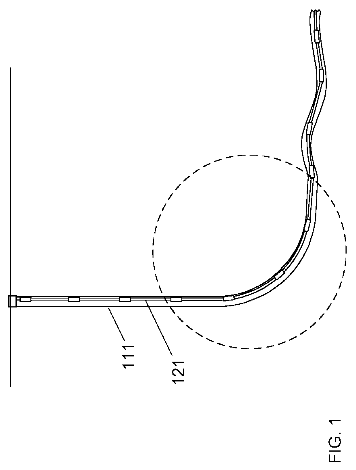
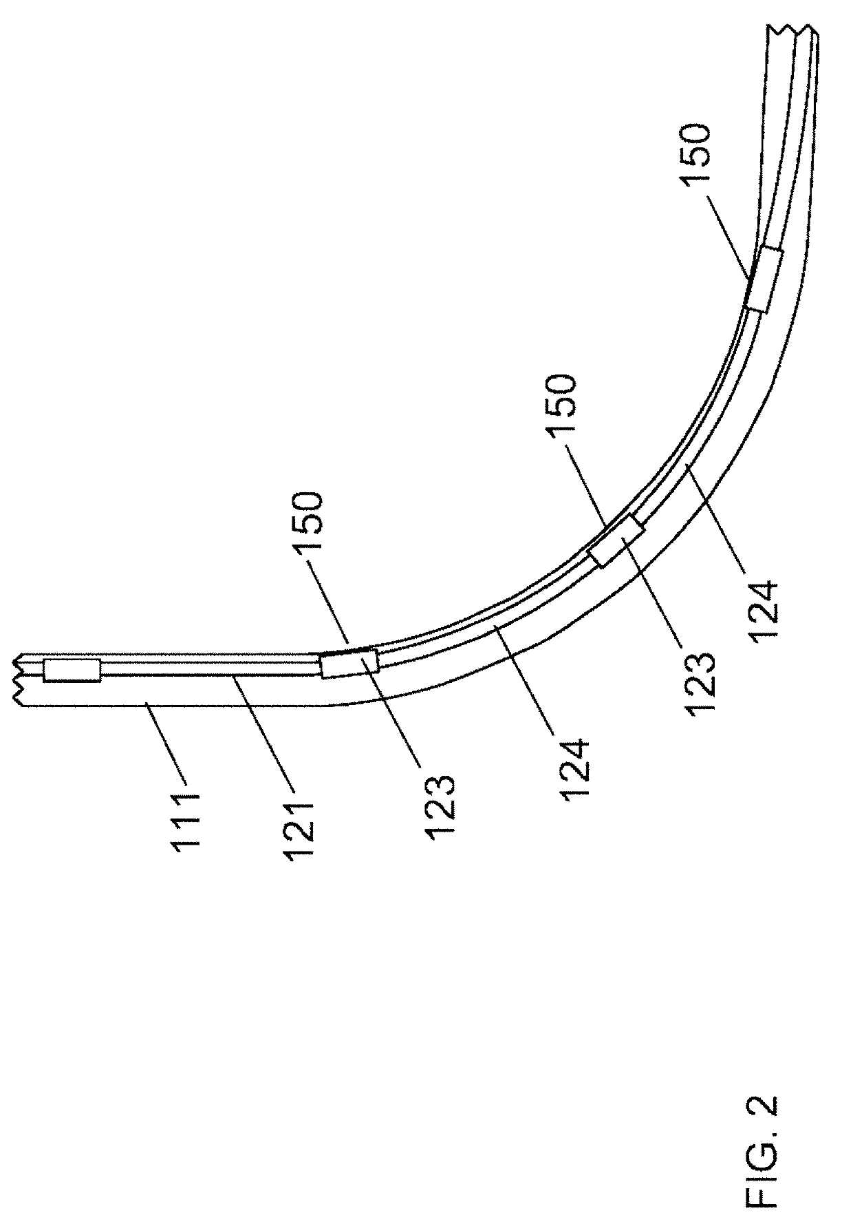
[0146]ToughMet® couplings were installed in ten deviated shale wells that had a history of elevated, frequent failure rates related to tubing / coupling failures. ToughMet® couplings with a 1 inch slim hole were only installed in deviated sections near the bottom of the well or near the surface of the well. These wells were typically 10,000 feet deep and deviated up to 10,000 feet in the horizontal direction. These wells ran about six pump strokes per minute and used L80 production tubing. The wells were evaluated for coupling failures in sections where the ToughMet® couplings were installed. The results of the failure evaluation are shown below in Table 5.
TABLE 5Well No.Days for no failures113862130231232413945107161064710648103591025101154
[0147]After 6 months in the well, some couplings were removed and visually observed. These inspected ToughMet® couplings showed no evidence of wear or metal transfer.
[0148]FIG. 9 illustrates the run time improvement of well no. 4. Installation of t...
PUM
| Property | Measurement | Unit |
|---|---|---|
| Fraction | aaaaa | aaaaa |
| Fraction | aaaaa | aaaaa |
| Fraction | aaaaa | aaaaa |
Abstract
Description
Claims
Application Information
 - R&D
- Intellectual Property
- Life Sciences
- Materials
- Tech Scout
- Unparalleled Data Quality
- Higher Quality Content
- 60% Fewer Hallucinations
Browse by: Latest US Patents, China's latest patents, Technical Efficacy Thesaurus, Application Domain, Technology Topic, Popular Technical Reports.
© 2025 PatSnap. All rights reserved.Legal|Privacy policy|Modern Slavery Act Transparency Statement|Sitemap|About US| Contact US: help@patsnap.com


