Fuel cell system and control method for fuel cell system

a fuel cell and control method technology, applied in the direction of electrical generators, vessel construction details, transportation and packaging, etc., can solve the problems of affecting the operation of the fuel cell system, and the residue liner might be damaged, so as to reduce the possibility, the effect of increasing the temperature and pressur

Active Publication Date: 2019-08-29
TOYOTA JIDOSHA KK
View PDF0 Cites 0 Cited by
  • Summary
  • Abstract
  • Description
  • Claims
  • Application Information

AI Technical Summary

Benefits of technology

[0006](1) A first aspect of this disclosure provides a fuel cell system. The fuel cell system includes a fuel cell stack, a high-pressure tank, an acquisition portion, a notification portion, and a controlling portion. The fuel cell stack is configured to generate electric power by consuming a fuel gas. The high-pressure tank includes a resin liner and a reinforcing layer configured to cover an outer surface of the resin liner. The high-pressure tank is filled with the fuel gas. The acquisition portion is configured to acquire a value of an internal pressure of the high-pressure tank and a value of an internal temperature that is a temperature inside the high-pressure tank. The notification portion is configured to notify that the high-pressure tank needs to be filled with the fuel gas. The controlling portion is configured to control an operation of the notification portion by use of the value of the internal temperature and the value of the internal pressure. The controlling portion sets, in a map of the internal temperature and the internal pressure, a boundary line sectioning the map into a first region and a second region. The first region indicates a possibility that a stress caused in the resin liner due to contraction of the resin liner damages the resin liner. The second region has a higher temperature and a higher pressure than the first region. When the value of the internal temperature and the value of the internal pressure reach the boundary line, the controlling portion causes the notification portion to notify that the high-pressure tank needs to be filled with the fuel gas. In the fuel cell system of this aspect, when the internal temperature and the internal pressure decrease and reach the boundary line, the controlling portion causes the notification portion to notify that the high-pressure tank needs to be filled with the fuel gas. This makes it possible to reduce the possibility that the resin liner is damaged due to a difference in contraction amount between the resin liner and the reinforcing layer. Here, that “the internal temperature and the internal pressure reach the boundary line” indicates that, in the map of the internal temperature and the internal pressure, a point formed by the value of the internal temperature and the value of the internal pressure reaches the boundary line, concretely, the point corresponds with one of points forming the boundary line or one of points falling within a side of the first region from the boundary line.
[0007](2) In the fuel cell system of the above aspect, when the value of the internal pressure reaches a predetermined threshold, the controlling portion may cause the notification portion to notify that the high-pressure tank needs to be filled with the fuel gas, regardless of whether the value of the internal temperature and the value of the internal pressure reach the boundary line or not. In the fuel cell system of this aspect, when an internal pressure condition is satisfied, the notification is executed regardless of whether the internal temperature and the internal pressure reach the boundary line or not. This makes it possible to restrain such a situation that the internal pressure largely decreases from the predetermined threshold. On this account, it is possible to reduce the possibility that electric power cannot be generated by the fuel cell stack due to insufficiency of the fuel gas.
[0008](3) In the fuel cell system of the above aspect, the resin liner may include a bonded part provided in a central part of the resin liner in the longitudinal direction of the resin liner so as to be bonded to the reinforcing layer. The stress may be caused in the resin liner at the bonded part due to contraction of the resin liner. With the fuel cell system of this aspect, it is possible to reduce the possibility that the resin liner is damaged by the stress caused in the bonded part due to contraction of the resin liner.

Problems solved by technology

The inventors of the present application found that, when an extremely contracted state of the resin liner and an extremely expanded state of the resin liner are repeated, an excessive stress is caused in the resin liner, so that the resin liner might be damaged.

Method used


Image

  • Fuel cell system and control method for fuel cell system
  • Fuel cell system and control method for fuel cell system
  • Fuel cell system and control method for fuel cell system

Examples


first embodiment

A. First Embodiment

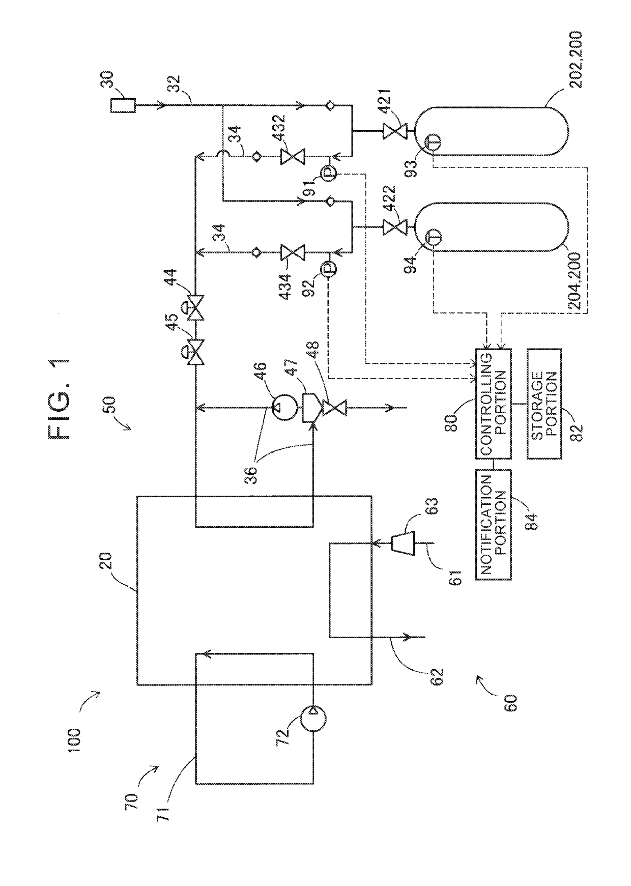
[0025]FIG. 1 is a diagrammatic view of a fuel cell system 100 according to the first embodiment. The fuel cell system 100 includes a fuel cell stack 20, a fuel gas supply / discharge mechanism 50, an oxidant gas supply / discharge mechanism 60, a refrigerant circulation mechanism 70, a controlling portion 80, a storage portion 82, and a notification portion 84. The fuel cell system 100 generates electric power by a reaction between a fuel gas (anode gas) and an oxidant gas (cathode gas). In the present embodiment, the fuel gas is hydrogen gas, and the oxidant gas is air.

[0026]The refrigerant circulation mechanism 70 is connected to the fuel cell stack 20 and includes a refrigerant circulation passage 71 through which a refrigerant (e.g., water) circulates and a pump 72 configured to send out the refrigerant. The oxidant gas supply / discharge mechanism 60 includes an oxidant gas supply passage 61 through which the oxidant gas is supplied to the fuel cell stack 20, and a...

second embodiment

B. Second Embodiment

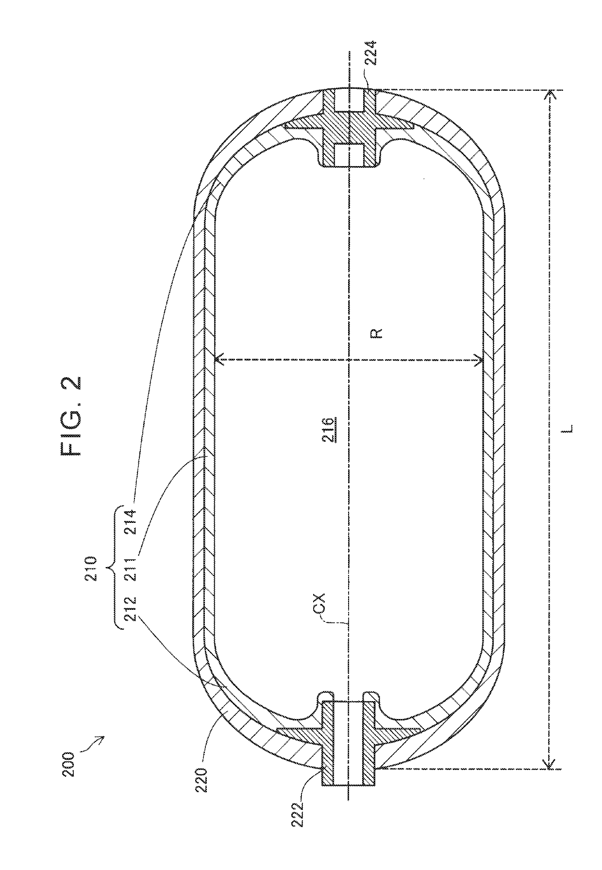
[0059]FIG. 5 is a schematic view of a high-pressure tank 400 according to the second embodiment. FIG. 5 illustrates a sectional structure obtained when the high-pressure tank 400 is cut along a central axis CX of the high-pressure tank 400. The high-pressure tank 400 used in the fuel cell system 100 of the second embodiment is different from the high-pressure tank 200 of the first embodiment in that a central part of the high-pressure tank 400 in its longitudinal direction is provided with a bonded part 410 where the resin liner 210 and the reinforcing layer 220 are bonded to each other over the circumferential direction of the resin liner 210. In the following description, the same constituent as that in the first embodiment has the same reference sign as in the first embodiment, and its detailed description is omitted.

[0060]The resin liner 210 and the reinforcing layer 220 at the bonded part 410 are bonded to each other, for example, such that a mold releasing ...


PUM

PropertyMeasurementUnit
Pressureaaaaaaaaaa
internal temperaturesaaaaaaaaaa
electric poweraaaaaaaaaa

Abstract

A fuel cell system includes: a high-pressure tank including a resin liner and a reinforcing layer; an acquisition portion configured to acquire a value of an internal pressure and a value of an internal temperature of the high-pressure tank; a notification portion; and a controlling portion. The controlling portion sets, in a map of the internal temperature and the internal pressure, a boundary line sectioning the map into a first region and a second region, the first region indicating a possibility that a stress caused in the resin liner damages the resin liner, the second region being a region having a higher temperature and a higher pressure than the first region. When the value of the internal temperature and the value of the internal pressure reach the boundary line, the controlling portion causes the notification portion to notify that the high-pressure tank needs to be filled with a fuel gas.

Description

INCORPORATION BY REFERENCE[0001]The disclosure of Japanese Patent Application No. 2018-031780 filed on Feb. 26, 2018 including the specification, drawings and abstract is incorporated herein by reference in its entirety.BACKGROUND1. Technical Field[0002]This disclosure relates to a fuel cell system and a control method for a fuel cell system.2. Description of Related Art[0003]There has been conventionally known a method for detecting a residual amount in a high-pressure hydrogen tank such that a hydrogen residual amount is estimated from a pressure inside the high-pressure hydrogen tank (e.g., Japanese Unexamined Patent Application Publication No. 2011-137545 (JP 2011-137545 A)).SUMMARY[0004]In a case where a tank including a resin liner and a reinforcing layer formed around the resin liner is used as a high-pressure hydrogen tank, it is known that the resin liner expands or contracts due to a change in an operating environment such as a temperature of the tank or an internal pressu...

Claims


Application Information

Patent Timeline
Patent Type & Authority Applications(United States)
IPC IPC(8): F17C1/02H01M8/04082
CPCF17C1/02H01M8/04201F17C2203/0604F17C2250/0631F17C2270/01F17C2203/012F17C2201/0104H01M8/04216H01M8/04373H01M8/04425H01M8/04738H01M8/04783F17C2201/056F17C2227/048F17C2203/0663F17C2223/0123F17C2203/0619F17C2250/043F17C2223/036F17C2221/012F17C2205/0397F17C2250/032F17C2203/0673F17C2205/0305F17C2201/054F17C2201/0109F17C2250/0439F17C2205/013F17C2227/046F17C2260/011F17C2265/066F17C2270/0184F17C2270/0178F17C2270/0189F17C2209/232F17C2250/077F17C1/16H01M8/04082H01M8/04365H01M2250/20Y02E60/32Y02T90/40Y02E60/50F17C2201/058F17C2203/066
Inventor OTSUBO, HIROKAZU
Owner TOYOTA JIDOSHA KK
Why Eureka
Try Eureka