Flow sensor based on electrical capacity

a technology of electrical capacity and flow sensor, applied in the direction of instruments, liquid/fluent solid measurement, resistance/reactance/impedence, etc., can solve the problems of varying the rate of application, the inability of liquid spray agricultural equipment to provide individual row sensing, and the economic disadvantage of tillage, planting and harvesting, so as to minimize the variation of material density over the time taken to traverse.

Active Publication Date: 2019-09-19
AMERICAN CHEM CORP
View PDF6 Cites 2 Cited by
  • Summary
  • Abstract
  • Description
  • Claims
  • Application Information

AI Technical Summary

Benefits of technology

[0019]The sensors placed on the sensing volume measure the electrical capacity of the substance within the sensing volume. Knowing the dielectric constant of the material (analyte) within the volume, a determination of the dielectric mass can be made, and thus an inference to the material mass within the volume. Knowing the mass and volume, the density of the material is easily extracted. To calculate a mass flow rate, all that is required is a velocity.
[0025]In the art, measurements using techniques other than capacity (permittivity) measurement for materials like anhydrous ammonia, the material is converted to a single phase, for example, by cooling, and then the material flow rate is measured. In applications such as an anhydrous ammonia applicator for crop (field) injection, one concern is uniformity of application between various rows formed by individual injectors. In that application, monitoring and / or controlling parameters such as pressure and / or temperature enhance the uniformity of measurement results.

Problems solved by technology

When insufficient anhydrous ammonia is applied to a crop row, that field strip (area) will not yield as it should and the costs incurred from tillage, planting, and harvesting are an economic disadvantage.
Additionally, liquid spray agricultural equipment does not provide for individual row sensing.
The bled vapor is often injected along with the measured ammonia resulting in over-application.
This results in varying rates of application due to many factors such as heating of the applicator hoses.
However, unless the hoses are held parallel to ground, anhydrous ammonia liquid will pool in low regions resulting in differential flow rates.
Also there is no easy way to tell if the hose on a particular row is plugged because the rate controller keeps the total rate constant even if an individual hose is plugged.
However, these systems are more costly and require more maintenance.
Augmenting such systems (hybrid systems) with delivery pumps to maintain pressure for higher rates is costly, as well as more complex, resulting in poorer reliablity.
These properties make flow sensing challenging.
Sensing the flow rate of particulate matter, such as grain has proven a challenge as well.
Inaccurate sensing of individual grains in a planter can result in overpopulation or sparse planting—neither of which is advantageous to the farmer.
Poor measurement of other substances may have alternate adverse impacts in other applications.

Method used


Image

  • Flow sensor based on electrical capacity
  • Flow sensor based on electrical capacity
  • Flow sensor based on electrical capacity

Examples


Embodiment Construction

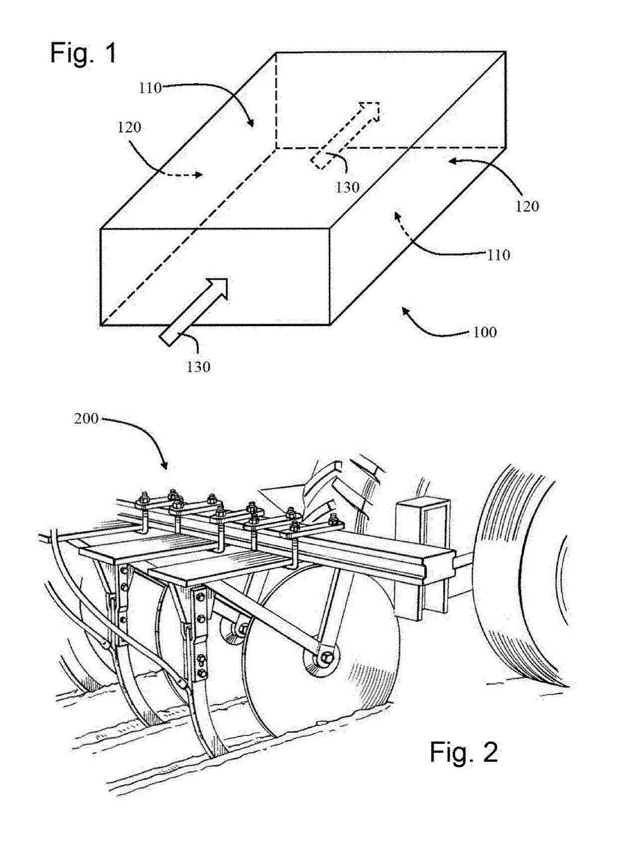
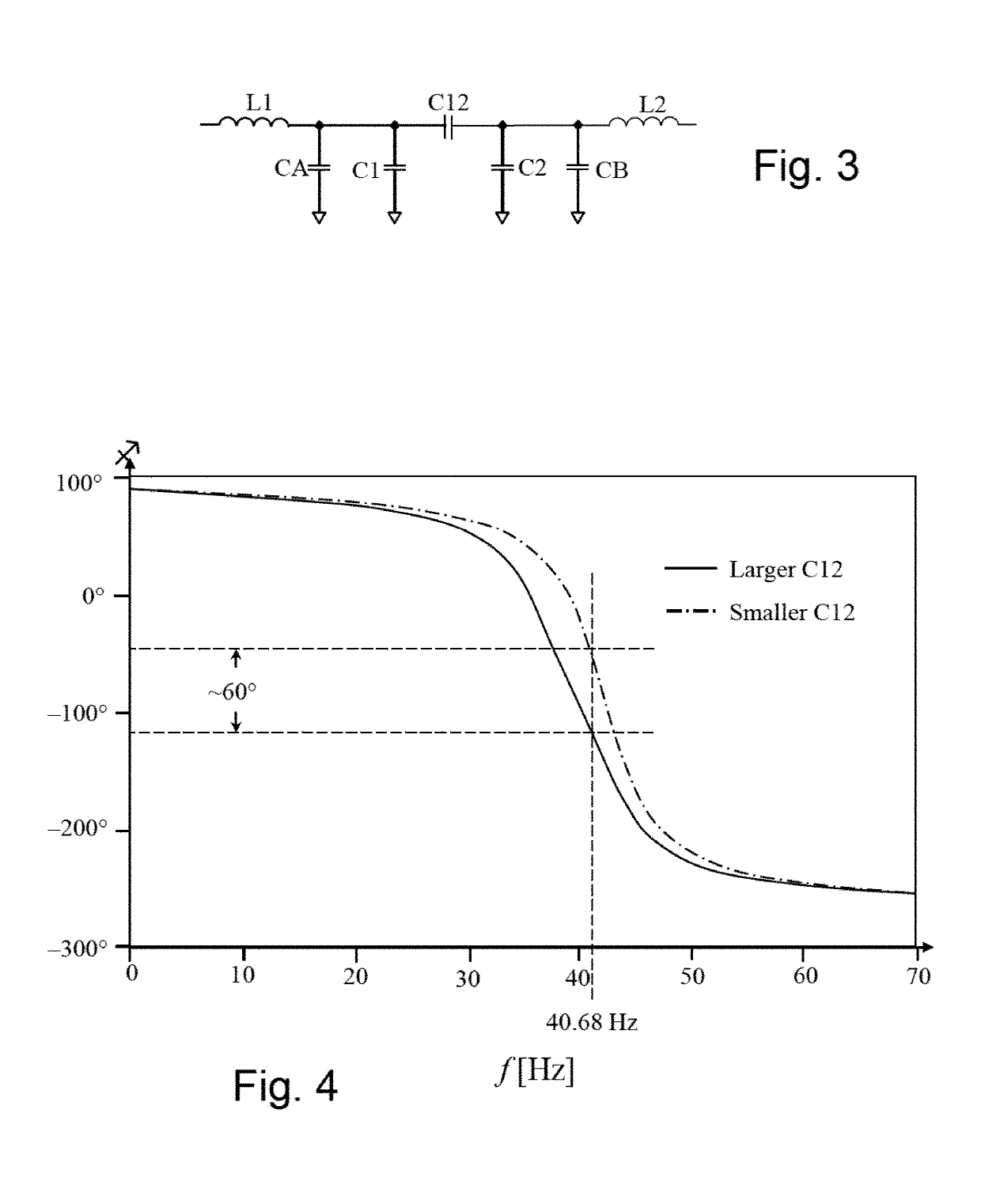
[0085]A sensor system volume 100 through which material may pass or in which material or matter is contained is shown in FIG. 1. Two sides 110 comprise electrically conducting plates. Two more sides 120 comprise electrical insulators. The capacity between the electrically conducting plates may be measured using methods commonly understood by those of ordinary skill in the art and explained in undergraduate electrical engineering texts. Circuits for this purpose are shown in FIGS. 3 and 5 and their use described below. The arrows 130 indicate a flow direction, but the direction is immaterial. In fact, there may be no flow at all. An application of the present invention is the sensing of mass flow rate of anhydrous ammonia using an applicator 200, an example of which is shown in FIG. 2. Such an applicator is made to apply anhydrous ammonia to multiple rows, simultaneously.

[0086]An example equivalent circuit of the sensor of the present invention is shown in FIG. 3. An input alternatin...


PUM

PropertyMeasurementUnit
electrically conductiveaaaaaaaaaa
distanceaaaaaaaaaa
time-delayaaaaaaaaaa

Abstract

An electric measurement method and apparatus for detecting a mass by an electric capacity (permittivity) or a material's dielectric constant, or alternatively, electric inductance (permeability). The mass may be any phase or combination of phases. The mass may be stationary or flowing. It may comprise discrete particles such as grain, or manufactured products such as ball bearings or threaded fasteners, etc. The mass may be a flow element in a rotameter or similar flow measurement device. The sensor comprises a volume which may be completely full or only partially full of the material. The material may be discrete components or a continuum. Sensor signals may be received by existing planter monitoring systems. In some embodiments the flow sensors are positioned external to the application port. In some embodiments sensors may be utilized which are responsive to the refractive index variation of specific chemicals.

Description

CROSS REFERENCE TO RELATED APPLICATIONS[0001]This application is a continuation-in-part of and claims priority of U.S. Ser. No. 14 / 037,680, filed Sep. 26, 2013. The entire contents of U.S. Ser. No. 14 / 037,680 is incorporated herein by reference in its entirety.BACKGROUND OF THE INVENTIONField of the Invention[0002]The present invention relates generally to a flow sensor. More particularly the present invention relates to a method and apparatus for sensing the flow rate of fluids, granular solids, and discrete particles by measuring electrical capacity for dielectric materials and magnetic permeability for magnetic materials.Background Art[0003]The dielectric constant of a first material is usually different than that of a second material. The dielectric constant for a substance may vary depending on the thermodynamic state of that substance, such as its state: solid, liquid, or vapor (gas). Therefore, the presence of a material may be detected by a process by which its effective die...

Claims


Application Information

Patent Timeline
Patent Type & Authority Applications(United States)
IPC IPC(8): G01F1/64G01D5/24G01N22/04G01F1/58G01F1/66G01F1/684G01R27/26G01F1/7088
CPCG01D5/2405G01F1/588G01R27/2635G01F1/6847G01F1/665G01N22/04G01N2011/0066G01F1/64G01F1/24G01F1/28G01F1/7088G01F1/712G01F1/74G01R27/2605G01R27/2641
Inventor CONRAD, LARRY M.WEBER, ROBERT J.
Owner AMERICAN CHEM CORP
Why Eureka
Try Eureka