Vertical take-off and landing aircraft and control method

a technology of vertical lift and aircraft, applied in the direction of vertical landing/take-off aircraft, airflow influencers, aircraft navigation control, etc., can solve the problems of aircraft fatal condition, reducing the overall vertical lift force that was supporting the aircraft's weight, and affecting the safety of passengers, so as to improve the control and stability of the aircraft

Inactive Publication Date: 2019-09-26
VEROPLANE INC
View PDF0 Cites 43 Cited by
  • Summary
  • Abstract
  • Description
  • Claims
  • Application Information

AI Technical Summary

Benefits of technology

[0009]This modification of the air flow during forward thrust allows the aircraft to significantly reduce drag. In particular, the presence of the rotor system in the airframe, in comparison to a standard winged aircraft, may otherwise be expected to produce more drag; embodiments of the invention can therefore mitigate or ameliorate this effect. The use of the rotor system in this way to influence, morph, moderate or shape the aerodynamic flow over the airframe effectively acts to move the aerodynamic centre of that portion of the airframe during the forward thrust mode. The actuation of the rotor system during forward thrust may be during the forward thrust mode itself, or during a transition to / from the vertical motion and forward thrust modes.
[0044]In an embodiment, the aircraft further comprises: a central flight processor for augmenting the control and stability of the aircraft during hovering operations, and through the transitional flight modes between hover operations and forward, wing-born flight operations as well.

Problems solved by technology

One of the major downfalls of this design is the dangerous time while the rotors are slowly tilting toward forward flight orientation.
As the rotors tilt, their overall vertical lift force that was supporting the aircraft's weight is quickly reduced while the wings do not yet have sufficient lift force generated yet during the relatively slow transition to the forward flight speed needed.
In these moments small anomalies, changes in wind speed or direction can stall the rotor(s), which is a possibly aircraft fatal condition for just a two-rotor equipped machine.
The same type of danger exists for redirected thrust type designs as they tilt thrust away from supporting the aircraft, but this concern is sometimes reduced due to the typically huge horsepower to weight ratio differences of these airframes.
In addition, previously considered systems have often not found satisfactory solutions to the problems of drag introduced by the incorporation of rotors into wing sections.
Moreover, various features of an airframe may increase drag in such arrangements.

Method used


Image

  • Vertical take-off and landing aircraft and control method
  • Vertical take-off and landing aircraft and control method
  • Vertical take-off and landing aircraft and control method

Examples


Embodiment Construction

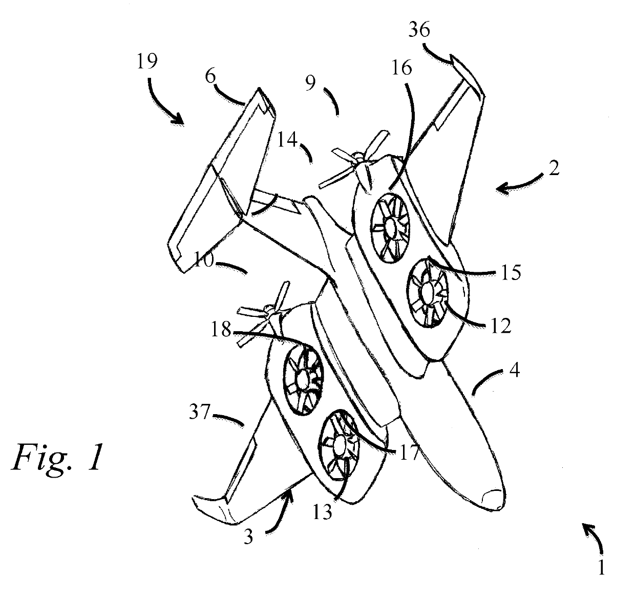
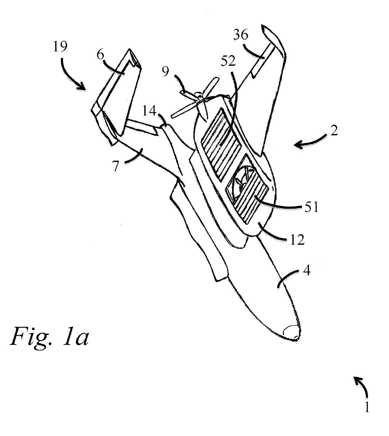
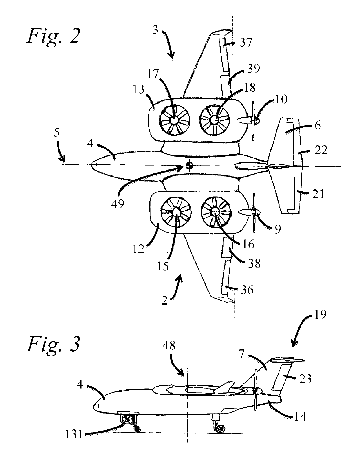
[0076]Embodiments of the invention can provide aircraft and systems in which modification of the air flow around the airframe, for example the wing section containing the rotors, can be effected by the rotors themselves, by making small adjustments to the rotors during forward flight. This allows dynamic alteration of the drag profile of the aircraft during forward flight, which in turn provides more efficient forward flight. Embodiments of the invention also provide enhanced stability in hover flight; increased ability to traverse adverse terrain conditions; while offering complete flexibility to perform vertical flight operations verses conventional forward flight, rolling take-offs and landings. These are aircraft configurations that offer similar efficiencies of fixed wing flight, while having the capability to take-off or land in a parking lot.

[0077]None of the previously considered systems can satisfy the substantially wider range of capabilities that the present embodiments' ...


PUM


Abstract

A vertical take-off and landing aircraft, and a control method for the aircraft, are disclosed. The aircraft has a vertical motion mode and a forward thrust mode. The aircraft comprises an airframe, having a wing section; a forward thrust means, for use during the forward thrust mode; a vertical lift rotor system, the rotor system being housed in a portion of the airframe; and a rotor control component configured to, during forward thrust, actuate the rotor system to modify the aerodynamic flow around the portion of the airframe housing the rotor system. Forward thrust may occur during the forward thrust mode, or other flight modes, such as transition phases to / from vertical motion and forward thrust modes. Modification of the aerodynamic flow may be used to optimize the aerodynamic flow around the portion of the airframe housing the rotor system.

Description

FIELD OF THE INVENTION[0001]This invention is directed to vertical take-off and landing aircraft, and control methods for such aircraft. Embodiments of the invention relate generally to specially designed fixed-wing aircraft configurations and more specifically to specialized vertical take-off and landing (VTOL) aircraft designs.BACKGROUND TO THE INVENTION[0002]There are many different types of VTOL aircraft designs. One well known method for accomplishing VTOL flight is via tilt-rotor designs where typically two (or more) larger propellers or rotors are mounted on pivoting axles at the ends of wingspans on these aircraft, and they then tilt or pivot from vertical orientation for lift off, to horizontal orientations as they transition through and enter normal forward flight mode. One of the major downfalls of this design is the dangerous time while the rotors are slowly tilting toward forward flight orientation. As the rotors tilt, their overall vertical lift force that was supporti...

Claims


Application Information

Patent Timeline
Patent Type & Authority Applications(United States)
IPC IPC(8): B64C27/30B64C27/20B64C27/26B64C29/00
CPCB64C27/30B64C2201/165B64C27/20B64C29/0025B64C2201/108B64C2201/021B64C27/26B64C21/00B64C39/024B64C2230/04B64D35/04B64C15/02Y02T50/10B64C5/02B64U30/10B64U10/25B64U30/20B64U50/13B64C27/22B64C29/0016
Inventor MORGAN, BRIAN
Owner VEROPLANE INC
Why Eureka
Try Eureka