Magnetic tunnel junction element and magnetic memory

a tunnel junction element and magnetic memory technology, applied in the direction of digital storage, galvano-magnetic material selection, instruments, etc., can solve the problems of large atomic weight of materials and easy damage of recording layers, and achieve high thermal stability, reduce power consumption, and increase density

Active Publication Date: 2019-10-03
TOHOKU UNIV
View PDF4 Cites 8 Cited by
  • Summary
  • Abstract
  • Description
  • Claims
  • Application Information

AI Technical Summary

Benefits of technology

[0015]However, in the MTJ element described in Non-Patent Literature 1, when a non-magnetic layer of Ta or the like inserted between the recording layers is heat-treated at such a high temperature as 350° C. or higher, Ta or the like diffuses in the recording layer and reaches a barrier layer to deteriorate the MR ratio. Furthermore, as the non-magnetic layer, high melting metal having high heat resistance, such as Ta and W, is used, but these materials have large atomic weight. Accordingly, in film formation by sputtering, materials such as Ta collide with the recording layer, and the recording layer may be easily damaged.
[0016]The present invention has been made by focusing on such problems, and has an object to provide a magnetic tunnel junction element having a higher MR ratio, and capable of preventing a recording layer from being damaged in film-formation, and a magnetic memory.

Problems solved by technology

Furthermore, as the non-magnetic layer, high melting metal having high heat resistance, such as Ta and W, is used, but these materials have large atomic weight.
Accordingly, in film formation by sputtering, materials such as Ta collide with the recording layer, and the recording layer may be easily damaged.

Method used


Image

  • Magnetic tunnel junction element and magnetic memory
  • Magnetic tunnel junction element and magnetic memory
  • Magnetic tunnel junction element and magnetic memory

Examples


example 1

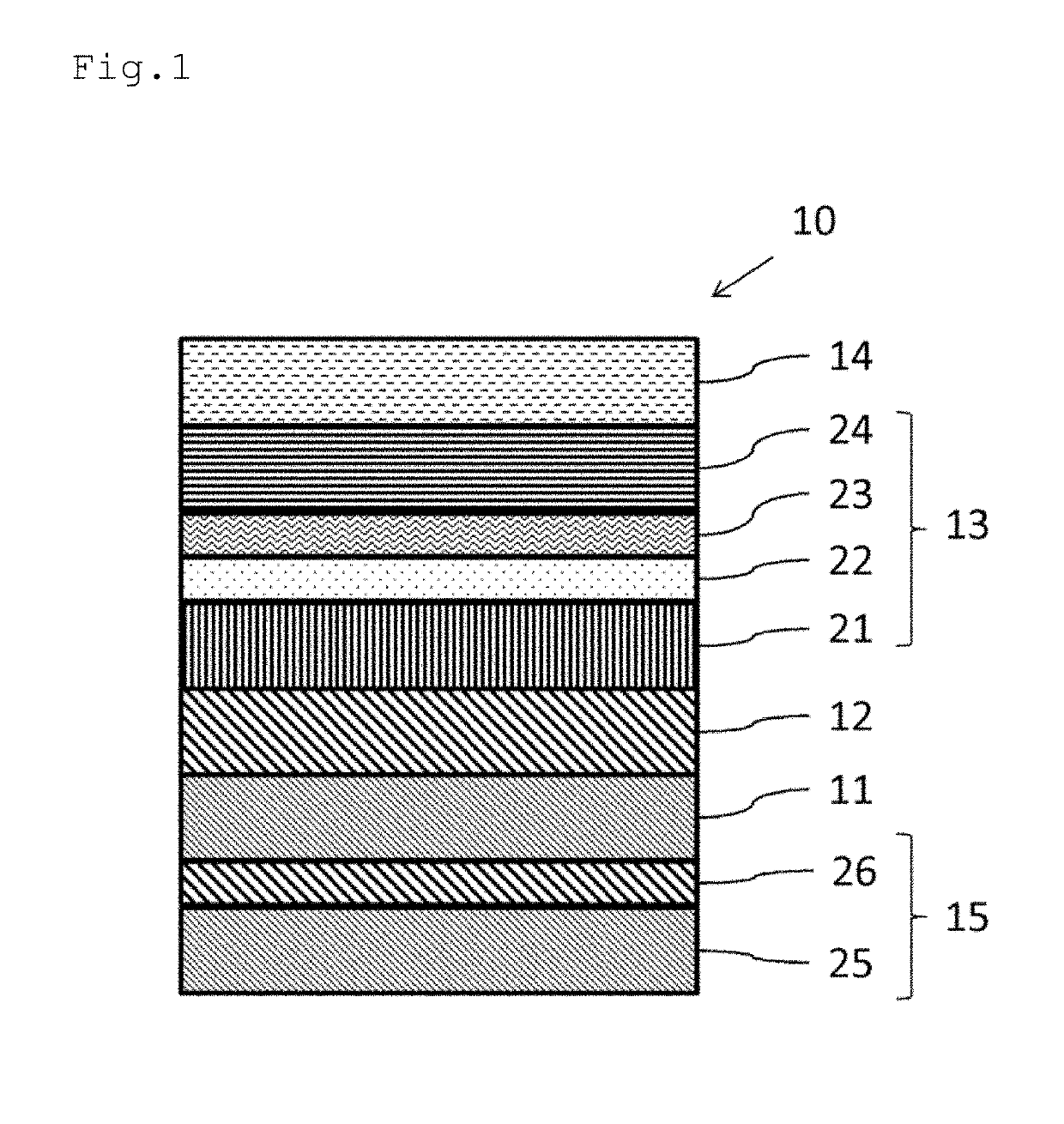
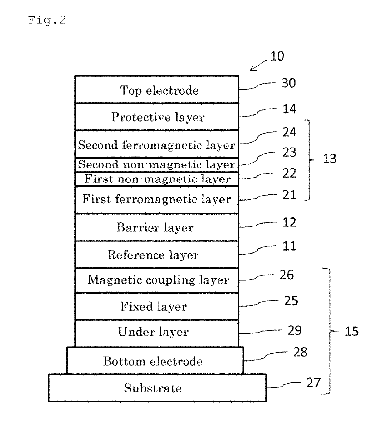
[0085]The magnetic property of a magnetic tunnel junction element 10 was measured with a thickness of a first non-magnetic layer 22 varied. As shown in FIG. 7, in the magnetic tunnel junction element 10 used for the measurement, a reference layer 11 has a thickness of 1 nm and is made of CoFeB, a barrier layer 12 has a thickness of 1.3 nm and is made of MgO, a first ferromagnetic layer 21 has a thickness of 1.4 nm and is made of CoFeB, the first non-magnetic layer 22 is made of MgO, a second non-magnetic layer 23 has a thickness of 0.4 nm and is made of Ta, a second ferromagnetic layer 24 has a thickness of 1.0 nm and is made of CoFeB, and a protective layer 14 has a thickness of 1.0 nm and is made of MgO. Furthermore, on a surface of the reference layer 11 opposite to the barrier layer 12, and on a surface of the protective layer 14 opposite to a second ferromagnetic layer 24, an electrode including a Ta layer having a thickness of 5 nm is formed, respectively. Note here that each ...

example 2

[0088]The magnetic property of the magnetic tunnel junction element 10 was measured with a thickness of a first non-magnetic layer 22 made of MgO and material and thickness of a second non-magnetic layer 23 varied. As shown in FIG. 9, the magnetic tunnel junction element 10 used for the measurement has a configuration in which a bottom electrode layer 28 including a Ta film having a thickness of 3 nm, a Ru film having a thickness of 20 nm, and a Ta film having a thickness of 3 nm, an under layer 29 having a thickness of 3 nm and made of Pt, a third ferromagnetic layer 31 formed by stacking a Co film having a thickness of 0.5 nm and a Pt film having a thickness of 0.3 nm four times, a third non-magnetic layer 33 formed by stacking a Co film having a thickness of 0.5 nm and a Ru film having a thickness of 0.9 nm, a fourth ferromagnetic layer 32 formed by staking a Co film having a thickness of 0.5 nm and a Pt film having a thickness of 0.3 nm twice, a magnetic coupling layer 26 formed...

example 3

[0096]The magnetic resistance (MR) ratio was measured with a size (diameter) of a magnetic tunnel junction element 10 varied. As shown in FIG. 12(a), the magnetic tunnel junction element 10 used for the measurement has a configuration in which a bottom electrode layer 28 including a Ta film having a thickness of 10 nm, a Ru film having a thickness of 5 nm, and a Ta film having a thickness of 5 nm, an under layer 29 having a thickness of 5 nm and made of Pt, a third ferromagnetic layer 31 formed by stacking a Co film having a thickness of 0.5 nm and a Pt film having a thickness of 0.3 nm four times, a third non-magnetic layer 33 formed by stacking a Co film having a thickness of 0.5 nm and a Ru film having a thickness of 0.9 nm, a fourth ferromagnetic layer 32 formed by staking a Co film having a thickness of 0.5 nm and a Pt film having a thickness of 0.3 nm twice, a magnetic coupling layer 26 formed by stacking a Co film having a thickness of 0.5 nm and a Ta film having a thickness ...


PUM


Abstract

A magnetic tunnel junction element with a high MR ratio, and can prevent a recording layer from being damaged, and magnetic memory. A reference layer includes a ferromagnetic body, and has magnetization direction fixed in the vertical direction. A barrier layer includes non-magnetic body, and disposed on one surface side of the reference layer. A recording layer is disposed to sandwich barrier layer between itself and reference layer. The recording layer includes a first ferromagnetic layer including at least one of Co and Fe, and having a magnetization direction variable in vertical direction; a first non-magnetic layer including at least one of Mg, MgO, C, Li, Al, and Si, second non-magnetic layer including at least one of Ta, Hf, W, Mo, Nb, Zr, Y, Sc, Ti, V, and Cr, and second ferromagnetic layer including at least one of Co and Fe, and having a magnetization direction variable in vertical direction.

Description

FIELD OF THE INVENTION[0001]The present invention relates to a magnetic tunnel junction element and a magnetic memory.DESCRIPTION OF RELATED ART[0002]The magnetization reversal using spin transfer torque (hereinafter, referred to as “STT”) is suitable for a memory element having high density and small power consumption, because a current value required for writing is reduced as the element size is smaller. In recent years, a magnetic memory using magnetization reversal by STT (STT-MRAM) has been drawing attention.[0003]The magnetic memory using magnetization reversal by STT includes a magnetic tunnel junction element (MTJ element). The MTJ element has a configuration in which a reference (fixed) layer whose magnetization direction is fixed and a recording (free) layer whose magnetization direction varies sandwich a tunnel barrier layer (tunnel insulating film).[0004]The performance of the MTJ element is represented by a tunnel magnetoresistance ratio (TMR ratio), thermal stability, ...

Claims


Application Information

Patent Timeline
Patent Type & Authority Applications(United States)
IPC IPC(8): G11C11/16H01L27/22H01L43/10
CPCG11C11/161G11C11/1657G11C11/1659G11C11/1675H01L27/228H01L43/08H01L43/10G11C11/1673G11C11/1655H01L43/02H01L27/105H01L29/82G11C11/18H10B61/22H10N50/85H10N50/10H10B99/00H10N50/80
Inventor HONJO, HIROAKIIKEDA, SHOJISATO, HIDEOENDOH, TETSUOOHNO, HIDEO
Owner TOHOKU UNIV
Why Eureka
Try Eureka