Integrated energy conversion, transfer and storage system

a technology of energy conversion and transfer, applied in the direction of braking system, fluid coupling, coupling, etc., can solve the problems of increasing consumption and emissions due to transient operating conditions, conventional brake energy recovery systems do not solve the efficiency problem, and conventional vehicles and industrial processes generate large amounts of waste heat, so as to improve the efficiency of energy systems, increase efficiency, and constant running conditions

Active Publication Date: 2019-10-03
A & A INT LLC
View PDF0 Cites 8 Cited by
  • Summary
  • Abstract
  • Description
  • Claims
  • Application Information

AI Technical Summary

Benefits of technology

[0024]Electrical output generation is also integrated. In addition to mechanical hydraulic energy generation, thermal energy is also converted into hydraulic energy and then into electrical or mechanical energy, according to the particular application. The embodiments are related to improving the efficiency of energy systems like vehicles, renewable energy

Problems solved by technology

Internal combustion engines for mobile applications must operate under a wide range of power conditions, which results in increased consumption and emissions due to transient operating conditions.
Conventional brake energy recovery systems do not solve the efficiency problem due to additional mass and limited usage.
These systems rely on the fuel combustion associated with harmful and greenhouse gas emissions.
Conventional vehicles and industrial processes generate large amounts of waste heat.
The current systems, however, have disadvantages in their operation due to efficiency, usability, flexibility, cost, applicability, weight, packaging, manufacturability, temperature range, recyclability and durability.
For internal combustion engine vehicles, however, it has been more difficult to implement regenerative braking systems because the energy conversion processes of internal combustion engines are difficult to reverse.
The process is often less efficient at low speeds due to fixed mechanical losses, such that regeneration is often replaced or supplemented by mechanical braking at low speeds.
At present, however, batteries are relatively expensive and have various drawbacks impeding their widespread adoption.
As with electric vehicles and batteries, however, these systems also tend to

Method used


Image

  • Integrated energy conversion, transfer and storage system
  • Integrated energy conversion, transfer and storage system
  • Integrated energy conversion, transfer and storage system

Examples


Embodiment Construction

[0150]In the following description, certain specific details are set forth in order to provide a thorough understanding of various disclosed embodiments. However, one skilled in the relevant art will recognize that embodiments may be practiced without one or more of these specific details, or with other methods, components, materials, etc. In other instances, well-known structures associated with the technology have not been shown or described in detail to avoid unnecessarily obscuring descriptions of the embodiments.

[0151]Unless the context requires otherwise, throughout the specification and claims that follow, the word “comprising” is synonymous with “including,” and is inclusive or open-ended (i.e., does not exclude additional, un-recited elements or method acts).

[0152]Reference throughout this specification to “one embodiment” or “an embodiment” means that a particular feature, structure or characteristic described in connection with the embodiment is included in at least one e...


PUM


Abstract

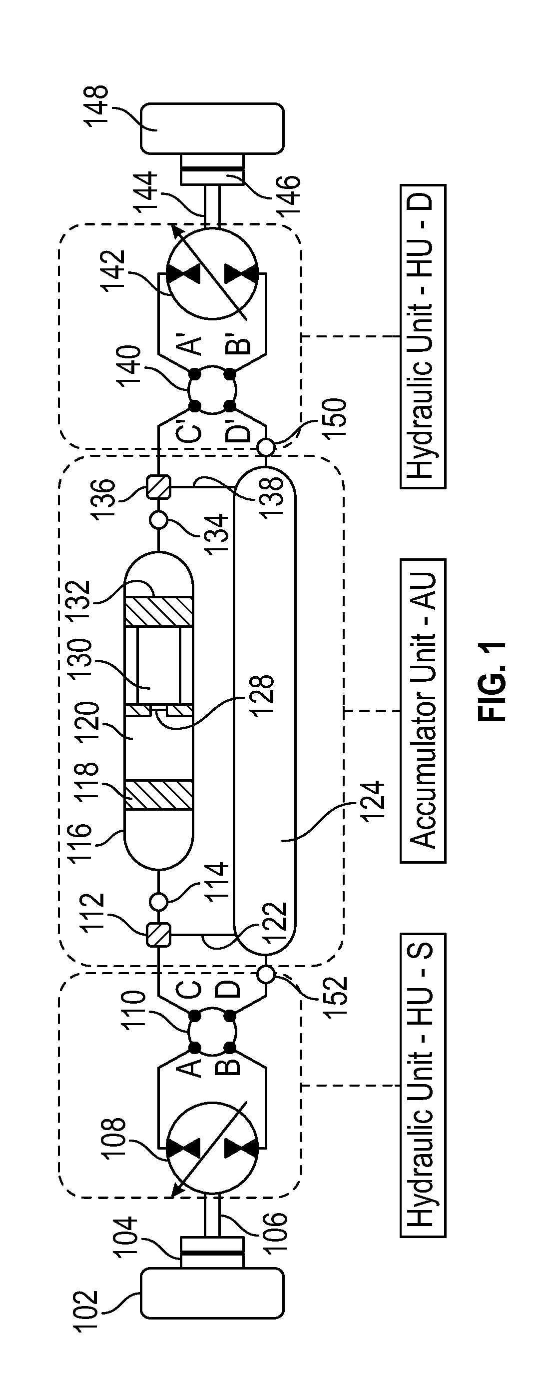
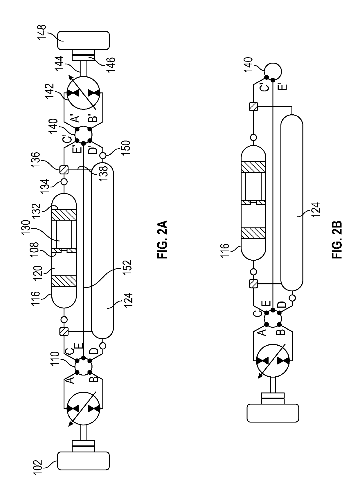
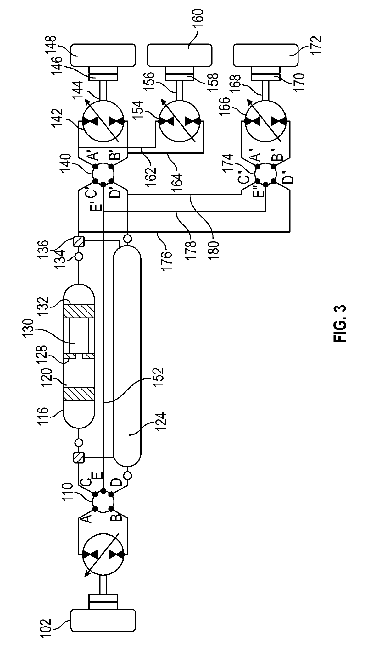
An integrated hybrid energy recovery and storage system for recovering and storing energy from multiple energy sources is disclosed. The system includes an accumulator unit having a high pressure accumulator and a low pressure accumulator. At least one piston is mounted for reciprocation in the high pressure accumulator. The accumulator unit is configured to receive, store, and transfer energy from the hydraulic fluid to the energy storage media. The system further includes two or more rotational directional control valves, in which at least one rotational directional control valve is positioned on each side of the accumulator unit. Each rotational directional control valve includes multiple ports. The system also includes two or more variable displacement hydraulic rotational units. At least one variable displacement hydraulic rotational unit is positioned adjacent each of the rotational directional control valves.

Description

TECHNICAL FIELD[0001]The present disclosure relates to an energy conversion, transfer, and storage system that is able to capture, store, and release energy according to the variable inputs outputs.BACKGROUNDDescription of the Related Art[0002]Current energy conversion systems rely on combustion processes, primarily internal combustion engines for mobile or stationary applications, or electrical motors powered by batteries or connected to an electrical network.[0003]These systems operate under variable conditions based on energy need and power generation requirements. Internal combustion engines for mobile applications must operate under a wide range of power conditions, which results in increased consumption and emissions due to transient operating conditions. Conventional brake energy recovery systems do not solve the efficiency problem due to additional mass and limited usage. The operation of an engine at a constant speed under different output conditions is a significant improv...

Claims


Application Information

Patent Timeline
IPC IPC(8): H02J3/28F16D31/02B60T1/10F15B1/027F15B1/04
CPCF16D31/02F15B1/04H02J3/28F15B1/027B60T1/10F15B1/024F15B1/265F15B21/14F15B2211/20546F15B2211/20569F15B2211/212F15B2211/625F15B2211/88F16D61/00Y02E60/16F16H61/44F16H61/4096
Inventor ABAITANCEI, HORIAMIHAI, CORNELIOANA, STEFAN
Owner A & A INT LLC
Why Eureka
Try Eureka