Detector for optically detecting at least one object

Active Publication Date: 2019-11-07
TRINAMIX GMBH
View PDF1 Cites 18 Cited by
  • Summary
  • Abstract
  • Description
  • Claims
  • Application Information

AI Technical Summary

Benefits of technology

The patent text describes a detector that can measure the distance and position of a light beam. It uses optical sensors that have a light-sensitive area to detect the beam. The detector can have multiple optical sensors to measure different aspects of the light beam. This device is simple and efficient to set up and can be used with commercially available sensors. Its combination of distance measurement and transversal coordinate detection makes it a versatile and useful tool for various applications.

Problems solved by technology

Because the laser energy is spread over a line, it is difficult to achieve accurate range, especially in the presence of ambient light, or with darker objects.
Such devices cannot be miniaturized, and their cost and mechanical fragility will remain high.
Although modulation techniques can be used to offset some of the effects of ambient light, PSDs do not perform well unless the laser spot has a very strong reflection, limiting their use to ranges of a meter or less.
Despite the advantages implied by the above-mentioned devices and detectors, several technical challenges remain.
Still, large area sensors in many cases are inherently limited in the use of the FiP measurement principle, specifically in case more than one light spot is to be investigated simultaneously.
A further challenge using FiP detectors is detector area or active area.
This area, however, may cause noise problems, specifically when the tetralateral conductivity concept is employed to build a PSD.
This often results in poor signal-to-noise-ratios and slow detector response times due to the large capacitance in conjunction with the series resistance of the detector.
A further challenge using FiP detectors is cost of manufacturing.
Thus, in many cases, typical FiP sensors are expensive, as compared to e.g. conventional Si-based photodiodes.
Further, the evaluation of the measurement results of measurements using FiP-sensors remains an issue, specifically in case the total power of a light beam is unknown.
Further, many FiP-detectors show a luminance dependency which renders the evaluation of the measurement result more difficult, and, additionally, FiP-measurements in many cases are dependent on a target spot size.
Referring to concepts comparing sensor signals generated by at least two different sources such as at least two different optical sensors, one technical challenge remains a reduction of cost of the overall system and, specifically, of the optical sensors.
Thus, in many concepts, special optical sensors have to be used, having a dedicated design and placement, which typically requires setting up an expensive optoelectronic semiconductor manufacturing process and a complex assembly scheme.

Method used


Image

  • Detector for optically detecting at least one object
  • Detector for optically detecting at least one object
  • Detector for optically detecting at least one object

Examples


Embodiment Construction

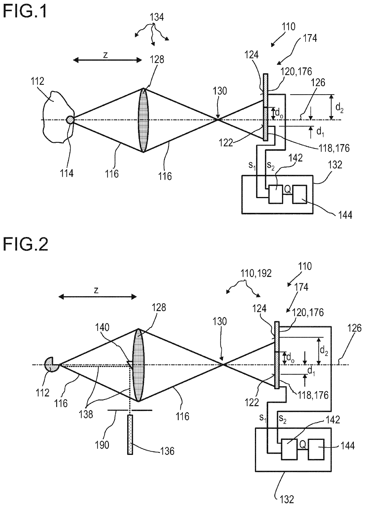
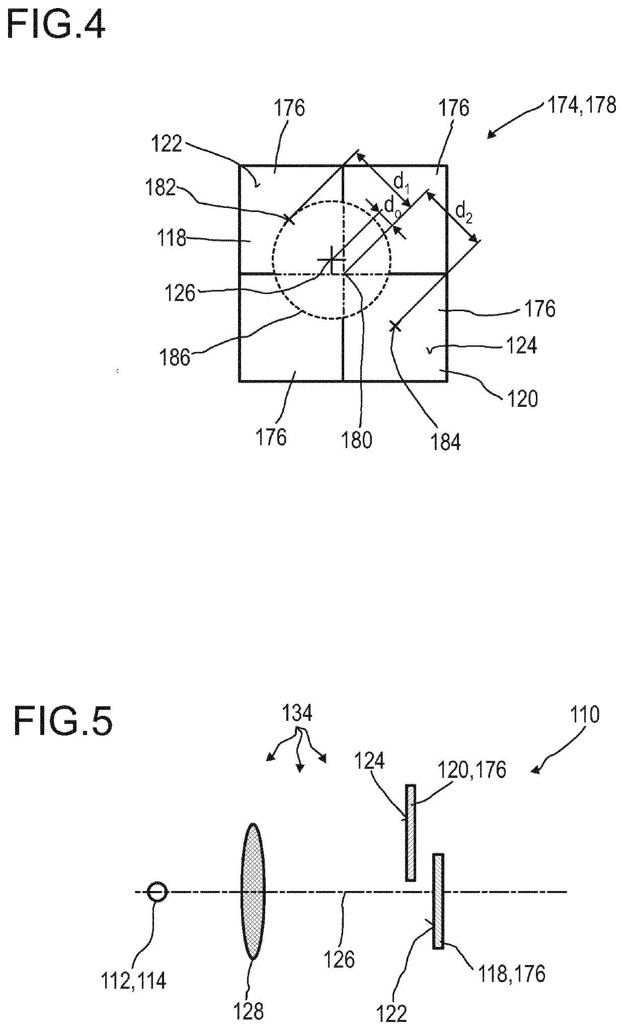
[0313]In FIG. 1, a schematic view of a first embodiment of a detector 110 for determining a position of at least one object 112 is depicted. In this case, the object 112 comprises a beacon device 114, from which a light beam 116 propagates towards a first optical sensor 118 and a second optical sensor 120. The first optical sensor 118 comprises a first light-sensitive area122, and the second optical sensor 120 comprises a second light-sensitive area 124. The optical sensors 118, 120, as shown e.g. in FIG. 4, may be part of an array 174 of optical sensors 176, such as the first optical sensor 118 being the optical sensor 176 in the upper left corner of the array 174 and the second optical sensor 120 being the optical sensor 176 in the lower right corner of the array 174. Other choices are feasible. The array 174, as an example, may be a quadrant photodiode 178, and the optical sensors 176 may be partial diodes of the quadrant photodiode 178.

[0314]The light beam 116, as an example, ma...


PUM


Abstract

A detector (110) for determining a position of at least one object (112) is proposed. The detector (110) comprises: —at least two optical sensors (118, 120, 176), each optical sensor (118, 120, 176) having a light-sensitive area (122, 124), wherein each light-sensitive area (122, 124) has a geometrical center (182, 184), wherein the geometrical centers (182, 184) of the optical sensors (118, 120, 176) are spaced apart from an optical axis (126) of the detector (110) by different spatial offsets, wherein each optical sensor (118, 120, 176) is configured to generate a sensor signal in response to an illumination of its respective light-sensitive area (122, 124) by a light beam (116) propagating from the object (112) to the detector (110); and—at least one evaluation device (132) being configured for determining at least one longitudinal coordinate z of the object (112) by combining the at least two sensor signals.

Description

FIELD OF THE INVENTION[0001]The invention relates to a detector, a detector system and a method for determining a position of at least one object. The invention further relates to a human-machine interface for exchanging at least one item of information between a user and a machine, an entertainment device, a tracking system, a camera, a scanning system, a readout device for optical storage media and various uses of the detector device. The devices, systems, methods and uses according to the present invention specifically may be employed for example in various areas of daily life, gaming, traffic technology, production technology, security technology, photography such as digital photography or video photography for arts, documentation or technical purposes, medical technology or in the sciences. Further, the invention specifically may be used for scanning one or more objects and / or for scanning a scenery, such as for generating a depth profile of an object or of a scenery, e.g. in t...

Claims


Application Information

Patent Timeline
IPC IPC(8): G01S5/16G01S11/12G01S17/46G01S17/36G01S7/481G01S17/32G01S17/89
CPCG01S17/46G01S11/12G01S17/36G01S7/4816G01S5/16G01S3/783G01S7/4808G01S7/4814G01B11/026G01J1/0411G01J1/0422G01J1/4228G01S7/4804G01S7/493G01S17/32G01S17/50G01S17/66G01S17/89
Inventor SCHILDKNECHT, CHRISTIANLUNGENSCHMIED, CHRISTOPHBRUDER, INGMAREBERSPACH, MICHAELFEJES, PETERSEND, ROBERTVALOUCH, SEBASTIANOHMER, THOMASHERMES, WILFRIEDHENGEN, STEFANLENNARTZ, CHRISTIAN
Owner TRINAMIX GMBH
Why Eureka
Try Eureka