Method of High-Efficient Heat Dissipation for Plasma Torch Electrode by Using Integrated Heat Pipes

Active Publication Date: 2019-11-07
INST NUCLEAR ENERGY RES ROCAEC
View PDF5 Cites 3 Cited by
  • Summary
  • Abstract
  • Description
  • Claims
  • Application Information

AI Technical Summary

Benefits of technology

The present invention is a method to improve heat dissipation in a plasma torch by incorporating heat pipes with high thermal conductivity into the torch electrode. This results in reduced electrode corrosion, increased lifetime for the torch, and lowered cost of maintenance. Additionally, the invention avoids and solves common problems encountered during torch usage, such as gas explosion and rock curing. The heat trickles through the electrode, allowing for efficient heat dissipation even if one of the heat pipes malfunctions. Overall, this method achieves higher heat dissipation efficiency and provides better safety and maintenance for the instrument and operator.

Problems solved by technology

Because about some portion of the main power of the torch falls on this small spot, usually the temperature at the arc spot is higher than the melting and boiling point of the electrode material, then part of the electrode material will be melted and evaporated due to this high temperature, and the metal particles evaporated further carry away with the working gas flow, which enhances and shortens the lifetime of the plasma torch and becomes the main obstacle that limits the applications of this technology.
Many improvement methods and techniques are studied and tried, for example, a magnetic field or a variable working airflow is used to guide and forced the movement of the arc root for preventing the arc root from being fixed at the same region of the electrode which would cause the electrode to be severely eroded in a short time, but usually this kind of improvement would cause the power fluctuation of the working torch.
Another method is to enhance the heat dissipation effect of the electrode with high-efficient, such as the designs of pressurized cooling-water and heat-dissipating channels and fins around the troch's electrode which used cooling-water channels for the high-pressure water located outside the electrode of the torch, but this also has its limits due to the maximum thermal conductivity that can be achieved.
But, in practical applications one problem occurred, a plasma melting furnace can be taken as an example for that, once the torch electrode is etched out with a small leak hole, high-pressured water that flows in the traditional cooling channels will be ejected into the plasma melting furnace in a great amount instantly.
There had a great opportunity of causing internal gas explosion which is not wanted in any case.
At the same time, the outflow of the cooling water also causes the to-be-treated molten liquid already existed in the plasma furnace to be cooled down suddenly and solidified instantly, which forms a major problem in the subsequent repair and re-operation of the plasma furnace.
Hence, the prior arts do not fulfill all users' requests on actual usage.

Method used


Image

  • Method of High-Efficient Heat Dissipation for Plasma Torch Electrode by Using Integrated Heat Pipes
  • Method of High-Efficient Heat Dissipation for Plasma Torch Electrode by Using Integrated Heat Pipes
  • Method of High-Efficient Heat Dissipation for Plasma Torch Electrode by Using Integrated Heat Pipes

Examples


Embodiment Construction

[0014]The following description of the preferred embodiment is provided to understand the features and the structures of the present invention.

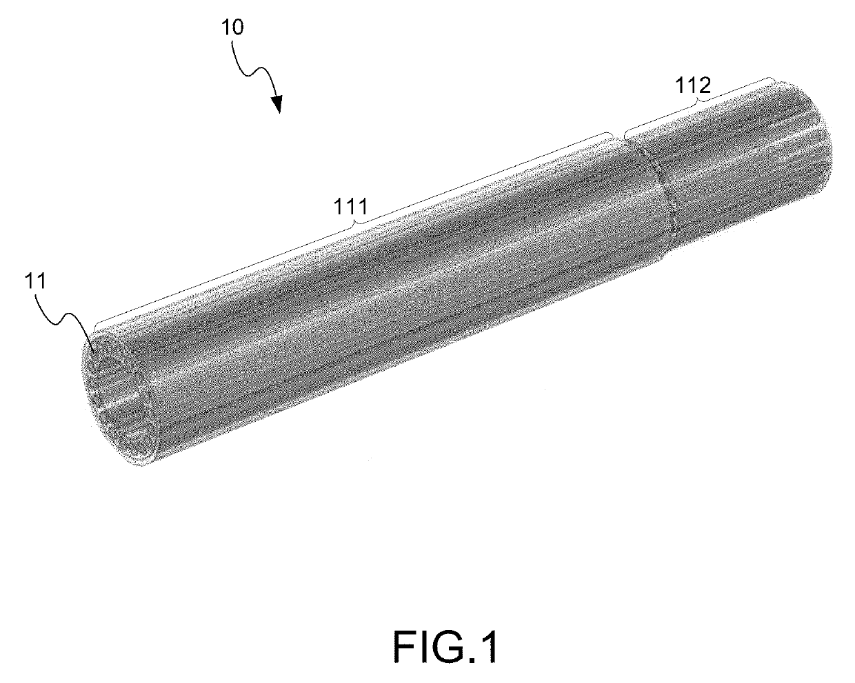
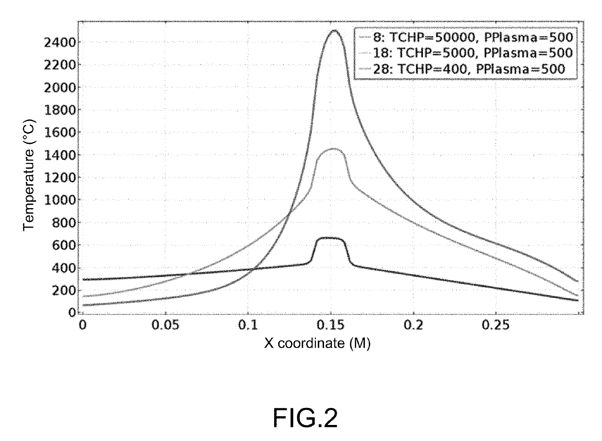
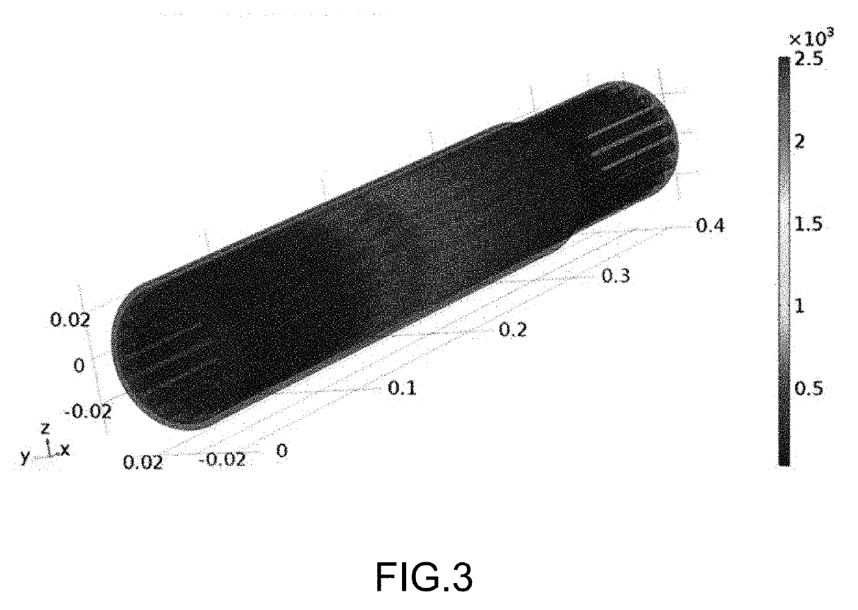
[0015]Please refer to FIG. 1˜FIG. 5, which are a view showing a torch electrode using a preferred embodiment according to the present invention; a view showing a curve of temperature distribution at axial direction on surface of an evaporating section; and views showing in 3D the temperature distributions of a torch electrode without heat pipes, and torch electrodes with heat pipes having thermal conductivity of 5,000 W / (m·K) and the best theoretical value 50,000 W / (m·K). As shown in the figures, the present invention is a method of high-efficient heat dissipation for a plasma torch electrode by using integrated heat pipes. The method uses heat pipes having ultra-high thermal conductivity to replace the existing water-cooled electrode which is still commonly adopted. According to the present invention, the heat pipes have better heat dissipat...


PUM


Abstract

Plasma torch with an integrated electrode incorporating many heat pipes each heat pipe comprises an evaporating section and a condensing section set at a front end and a rear end of the electrode, respectively. The heat pipes with extremely high thermal conductivity can be used to replace the traditional water-cooled torch's electrode. The effect of reducing the elevated temperature at the torch's arc root zone through cooling by heat pipes is beneficial for prolonging the lifetime of plasma torch. Each heat pipe is filled with a small amount of working fluid. Even if one heat pipe is etched out, the cooling liquid thus ejected is limited without causing gas explosion and rock curing; the rest of heat pipes are not damage and can still function; although the heat dissipation efficiency might be reduced a little, the plasma torch still works. Thus, flexibility of the whole heat dissipation is enhanced.

Description

TECHNICAL FIELD OF THE INVENTION[0001]The present invention relates to a method of improving heat dissipation of a plasma torch electrode; more particularly, to applying heat pipes circularly inside the plasma torch electrode to achieve high-efficiency heat dissipation, where each one of the heat pipes comprises an evaporating section at a front end and a condensing section at a rear end; and the heat pipes for the cooling for torch electrode have the merit of very high thermal conductivity so that the traditional water-flow cooled electrode with passage can be replaced with the effect of a lowered temperature at the center of arc root, thus enhanced heat dissipation efficiency, reduced electrode corrosion, prolonged lifetime for plasma torch, lengthened service cycle, and further lowered the cost of maintenance.DESCRIPTION OF THE RELATED ARTS[0002]Plasma Torches for high temperature applications is a core technology relied heavily on power electronic equipment and auxiliary system....

Claims


Application Information

Patent Timeline
IPC IPC(8): H05H1/28F28D15/02F28D15/04
CPCF28D15/04H05H1/28F28D15/0275
Inventor CHEN, SHIAW-HUEILEE, HOW-MING
Owner INST NUCLEAR ENERGY RES ROCAEC
Why Eureka
Try Eureka