
Apparatus and method for controlling of steer by wire system

Active Publication Date: 2019-12-05
HL MANDO CORP
View PDF0 Cites 11 Cited by
  • Summary
  • Abstract
  • Description
  • Claims
  • Application Information

AI Technical Summary

Benefits of technology

The present invention provides a way to prevent damage to vehicles and minimize noise by controlling the movement of the racks. This results in better control and stability of the vehicle's behavior, while also making it easier for drivers to restrict the rack movement.

Problems solved by technology

In a rack-pinion type steer-by-wire system generally used, in the case that the driver turns the steering wheel to one end, the stoppers of the rack bar and the ends of the gearbox housing may contact each other, and a collision due to the inertial motion of the rack may occur.
As a result, noise and vibration of the vehicle may be generated, thereby causing a discomfort to the driver and shortening the life of the vehicle due to mechanical damage
However, this prior art may not take into consideration the external force received by the vehicle, and may only provide the same rack stroke control value for a predetermined target steering angle.
Therefore, in a situation in which the vehicle receives an external force, the actual steering angle of the vehicle may increase or decrease more than the target steering angle, and as a result, there may be a problem the steering feeling for the driver changes.
In addition, to solve this problem, a method of adding a hardware device to a reaction force motor may have a problem of an increase in production cost.
In addition, in the method of applying a strong reverse current to the reaction force motor, there may be a problem that the sense of difference of the driver's steering feeling may increase in applying the strong reverse current.

Method used


Image

  • Apparatus and method for controlling of steer by wire system
  • Apparatus and method for controlling of steer by wire system
  • Apparatus and method for controlling of steer by wire system

Examples


Embodiment Construction

[0025]In the following description of examples or embodiments, reference will be made to the accompanying drawings in which it is shown by way of illustration specific examples or embodiments that can be implemented, and in which the same reference numerals and signs can be used to designate the same or like components even when they are shown in different accompanying drawings from one another.

[0026]Further, in the following description of the present disclosure, detailed descriptions of well-known functions and components incorporated herein will be omitted when it is determined that the description may make the subject matter in some embodiments of the present disclosure rather unclear.

[0027]The terms such as “including”, “having”, “containing”, “constituting”“make up of”, and “formed of” used herein are generally intended to allow other components to be added unless the terms are used with the term “only”. As used herein, singular forms are intended to include plural forms unles...


PUM


Abstract

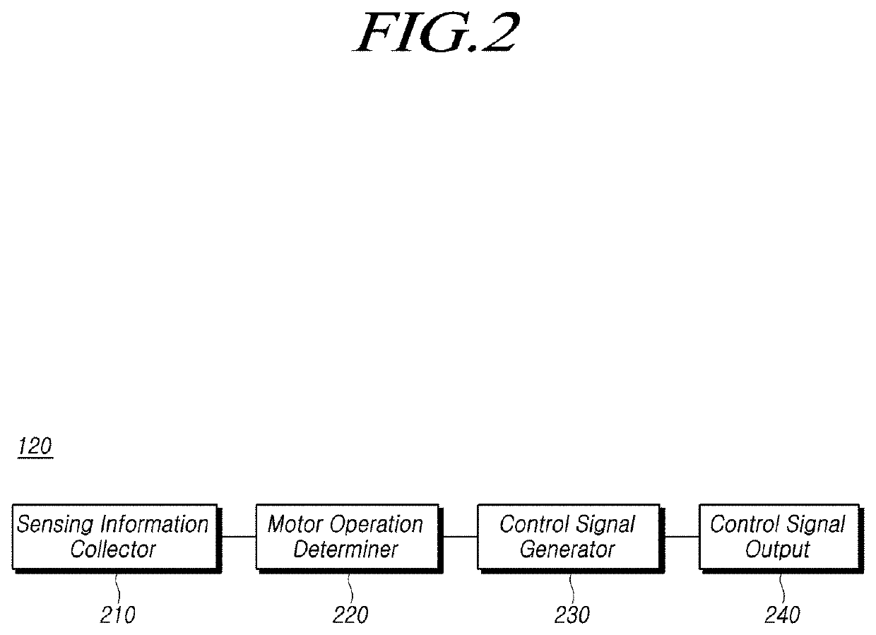
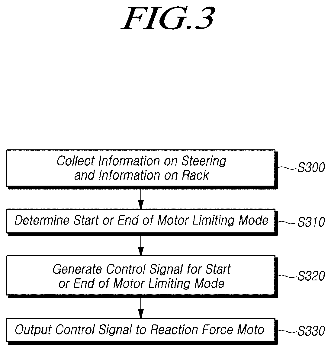
The present disclosure relates to a steering control apparatus and method of the steer-by-wire system including a sensing information collector for collecting at least one of sensing information on a steering or sensing information on a rack, a motor operation determiner for determining a start of a motor limiting mode for a reaction force motor and an end of the motor limiting mode for the reaction force motor which provides a reaction torque to a steering wheel based on the collected sensing information, a control signal generator for generating a control signal corresponding to the start of the motor limiting mode or the end of the motor limiting mode based on the determined result, and a control signal output for outputting the generated control signal to the reaction force motor.

Description

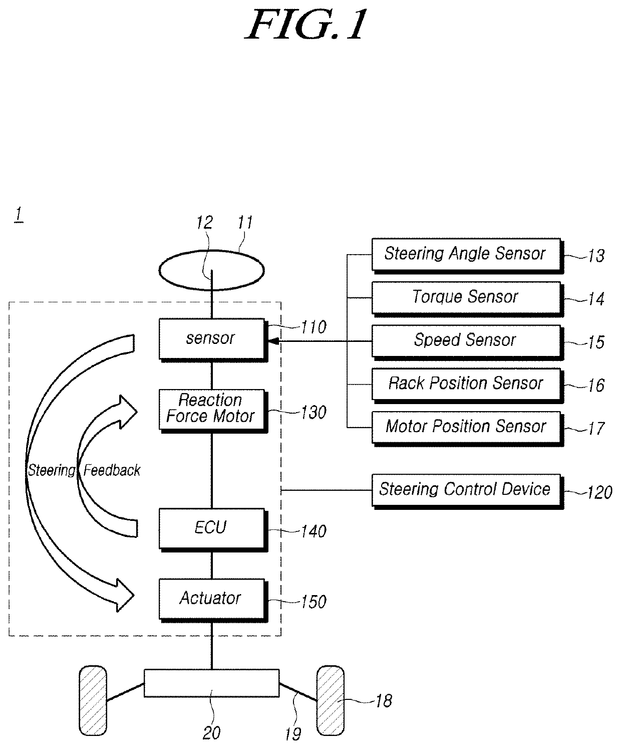
CROSS REFERENCE TO RELATED APPLICATION[0001]This application claims priority from Korean Patent Application No. 10-2018-0061343, filed on May 29, 2018, which is hereby incorporated by reference for all purposes as if fully set forth herein.BACKGROUND OF THE INVENTION1. Field of the Invention[0002]The present disclosure relates to a steering control apparatus and method for a steer-by-wire system, and more particularly, to a steering control apparatus and a control method for controlling a reaction force motor of a steering wheel, thereby limiting a rack stroke.2. Description of the Prior Art[0003]The steering-by-wire system is a steering system which eliminates the mechanical connection structure between the steering wheel and the vehicle wheel, constitutes the actuators on both vehicle wheels, thereby controls the actuator by an electrical signal according to the rotation of the steering wheel.[0004]Specifically, the steer-by-wire type steering system may comprise a steering wheel ...

Claims


Application Information

Patent Timeline
IPC IPC(8): B62D6/00B62D15/02B62D5/04
CPCB62D6/008B62D15/0225B62D5/0469B62D5/046B62D5/0463B62D5/006B60W2510/20B60Y2400/405B60Y2400/4187B60Y2400/301B60Y2400/307B60Y2400/303
Inventor HONG, SEUNGGYU
Owner HL MANDO CORP
Learn More