
Ultrasonic probe and manufacturing method thereof

a technology of ultrasonic probes and manufacturing methods, applied in ultrasonic/sonic/infrasonic diagnostics, mechanical vibration separation, device material selection, etc., can solve the problems of deteriorating the performance of ultrasonic probes, and affecting the reliability of ultrasonic probes. , to achieve the effect of preventing aging failure of ultrasonic probes and improving the reliability of ultrasonic probes

Inactive Publication Date: 2019-12-26
SAMSUNG MEDISON
View PDF0 Cites 1 Cited by
  • Summary
  • Abstract
  • Description
  • Claims
  • Application Information

AI Technical Summary

Benefits of technology

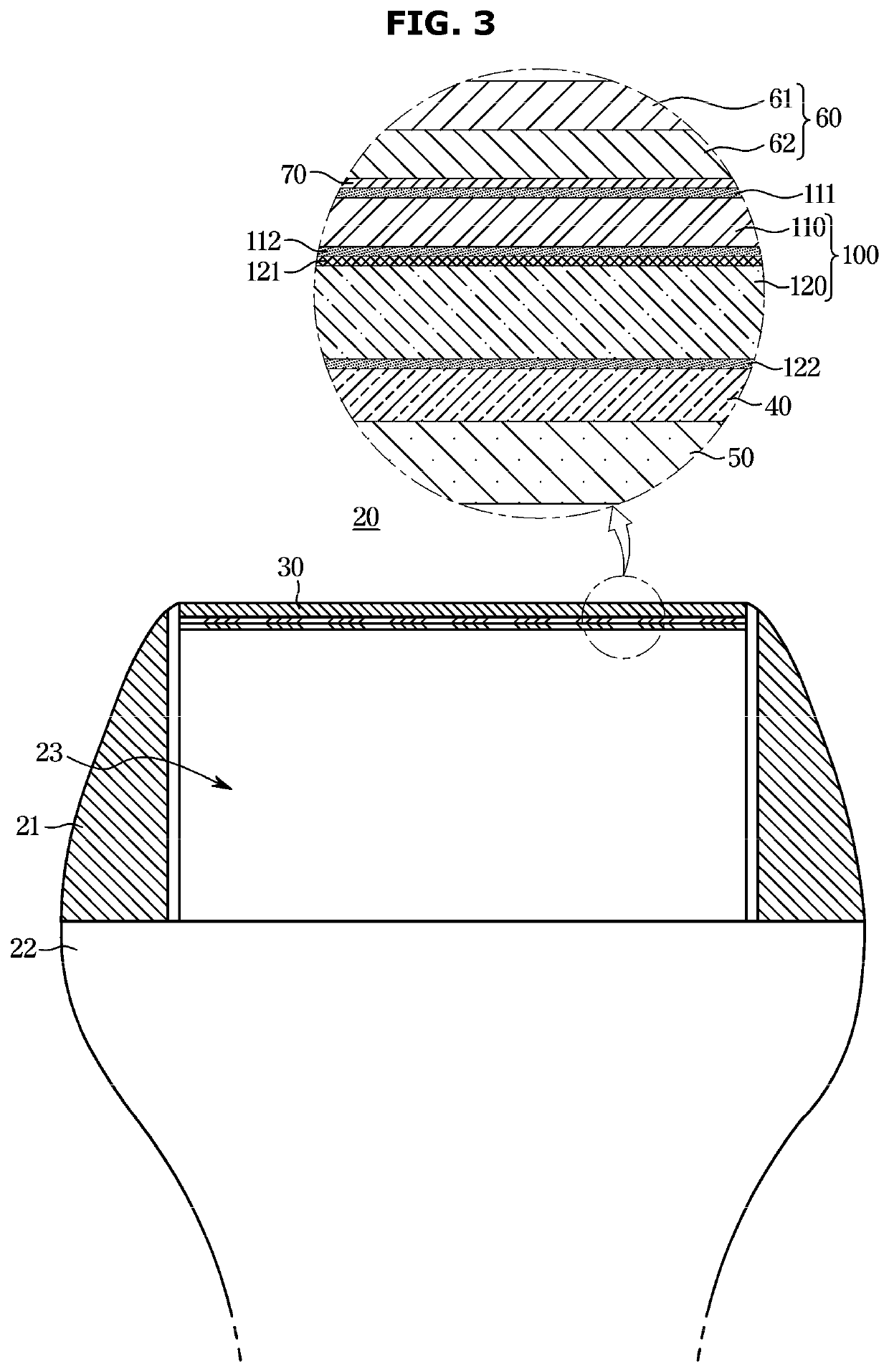
The patent describes an improved ultrasonic probe that can prevent aging failure and cutting damage. The probe includes a transducer layer with a piezoelectric layer and an acoustic layer, and a matching layer. The transducer layer has a stepped portion to prevent cutting damage and a damage portion to further protect the active portion. Additionally, the piezoelectric layer may have a cut portion near its edge to prevent cutting damage. These improvements enhance the reliability and quality of the ultrasonic probe.

Problems solved by technology

The performance of PZT ceramics may be improved, but the performance improvement may be limited.
On the other hand, in cutting machining by rotation, a rotation shaft of a cutting machine may be accompanied by minute tremors, whereby cutting damage such as chipping or cracks may occur on a cut surface of the single crystal having a relatively high brittleness.
The cutting damage may deteriorate the performance of the ultrasonic probe and may cause aging defects or the like, which may deteriorate the reliability in the quality of the ultrasonic probe.
In particular, when the single crystal is processed in a single state by a cutting machine, the frequency of cutting damage occurring in the single crystal may be increased.

Method used


Image

  • Ultrasonic probe and manufacturing method thereof
  • Ultrasonic probe and manufacturing method thereof
  • Ultrasonic probe and manufacturing method thereof

Examples


Embodiment Construction

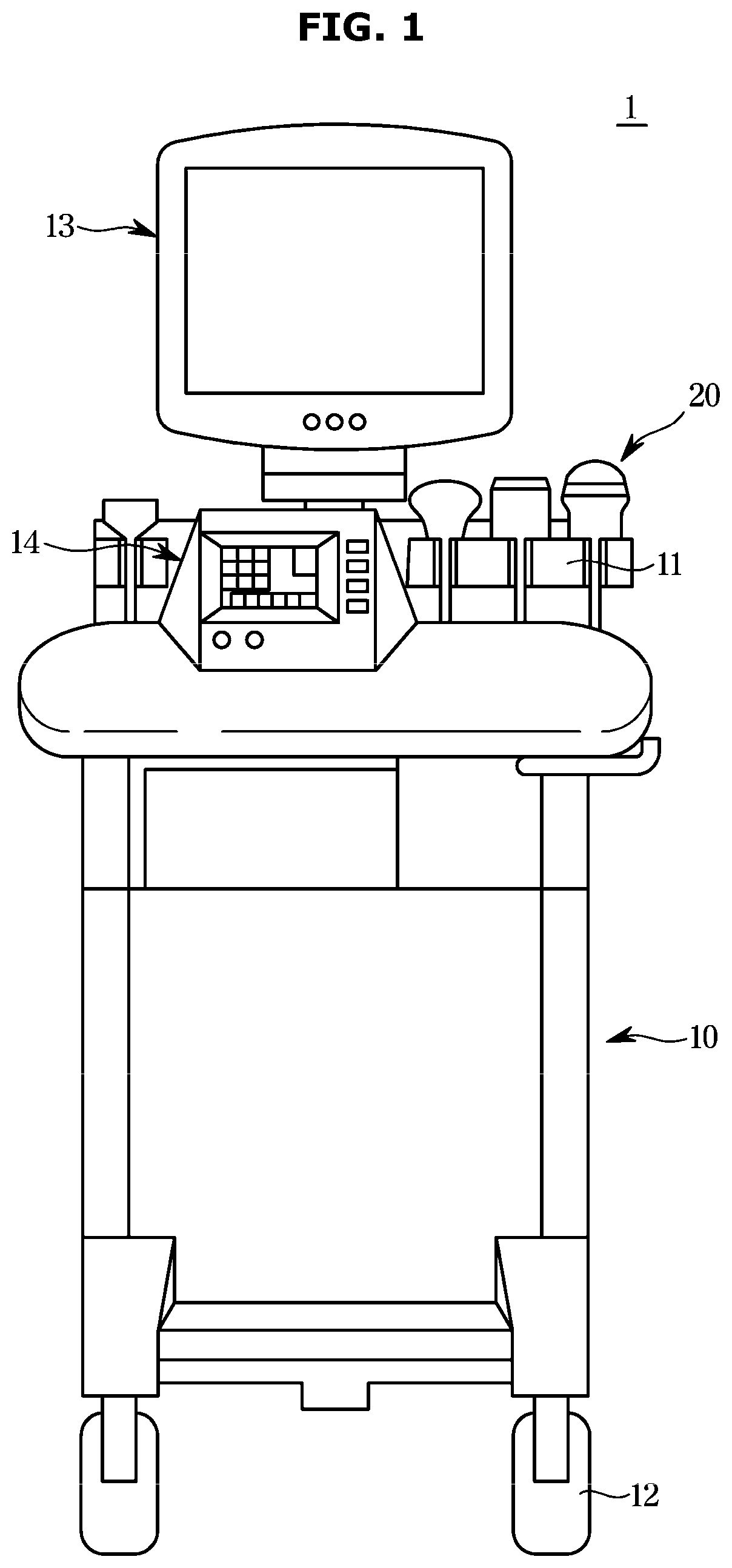
[0048]The embodiments described in the present specification and the configurations shown in the drawings are only examples of preferred embodiments of the disclosure, and various modifications may be made at the time of filing of the disclosure to replace the embodiments and drawings of the present specification.

[0049]Like reference numerals or signs in the respective drawings of the present specification represent parts or components that perform substantially the same functions.

[0050]The terms used in the present specification are for the purpose of describing the embodiments and are not intended to restrict and / or to limit the disclosure. For example, the singular expressions herein may include plural expressions, unless the context clearly dictates otherwise.

[0051]The terms “comprises” and “has” are intended to indicate that there are features, numbers, steps, operations, elements, parts, or combinations thereof described in the specification, and do not exclude the presence or...


PUM


Abstract

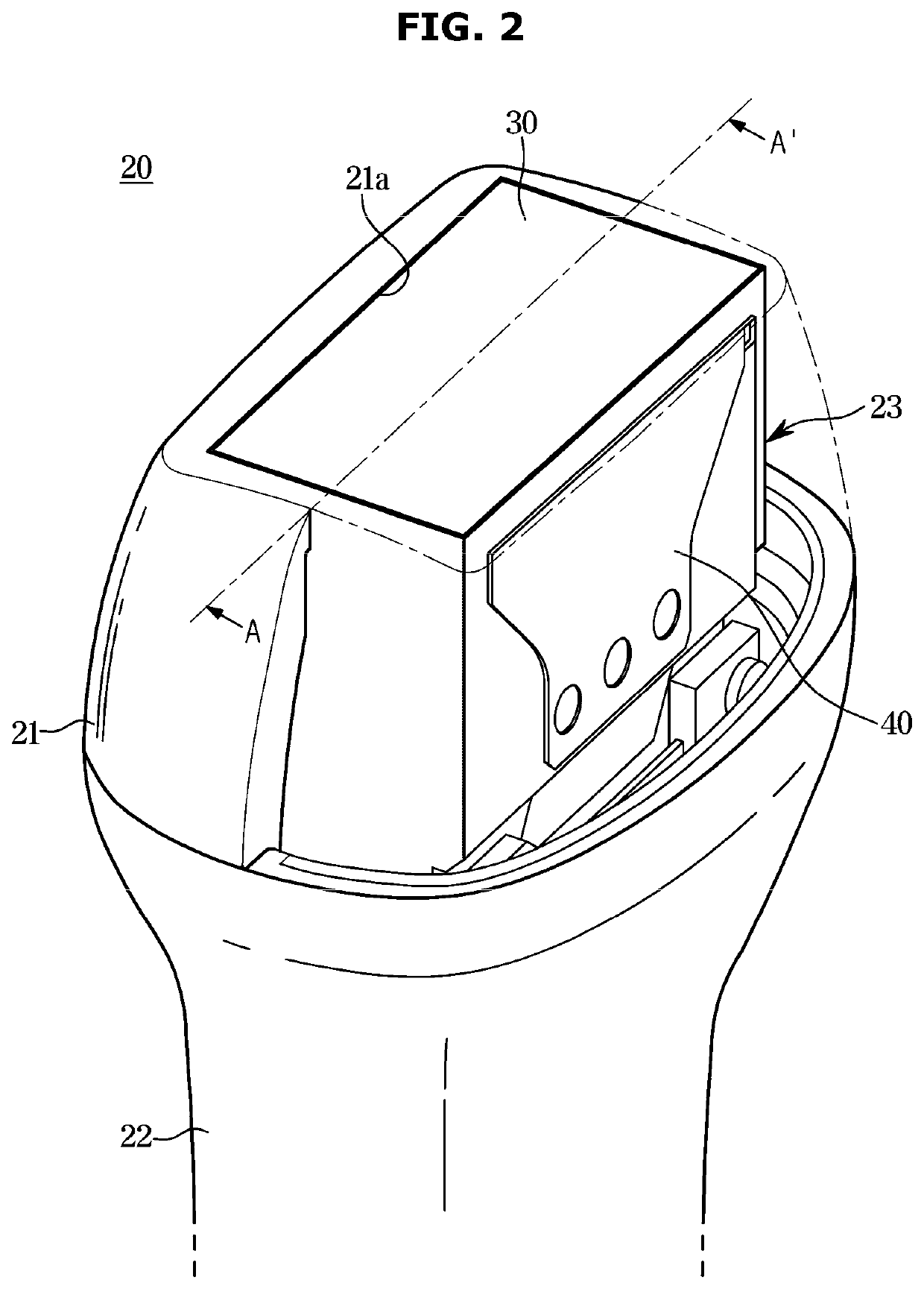
Disclosed are an ultrasonic probe for obtaining an ultrasonic image and a manufacturing method thereof. The ultrasonic probe includes a transducer layer including a piezoelectric layer configured to generate ultrasonic waves and an acoustic layer disposed below the piezoelectric layer, and a matching layer disposed above the piezoelectric layer, wherein the transducer layer includes an active portion configured to transmit and receive ultrasonic waves, and a stepped portion extending outward from the active portion to prevent cutting damage of the active portion.

Description

CROSS-REFERENCE TO RELATED APPLICATION(S)[0001]This application is based on and claims priority under 35 U.S.C. § 119 to Korean Patent Application No. 10-2018-0070806, filed on Jun. 20, 2018, in the Korean Intellectual Property Office, the disclosure of which is incorporated by reference herein in its entirety.BACKGROUND1. Technical Field[0002]The disclosure relates to an ultrasonic probe for obtaining an ultrasonic image and a manufacturing method thereof.2. Description of the Related Art[0003]An ultrasonic imaging apparatus is an apparatus that irradiates an ultrasonic signal from a body surface of a target toward a target site in the body and obtains an image of a monolayer or blood flow of soft tissue without invasion by using information of a reflected ultrasonic signal (ultrasonic echo signal).[0004]The ultrasonic imaging apparatus is small, inexpensive, real-time displayable, easy to use, and has a high level of safety because there is no radiation exposure, compared to other...

Claims


Application Information

Patent Timeline
IPC IPC(8): H01L41/113H01L41/25H01L41/338B06B1/06B06B3/00H01L41/18A61B8/00
CPCH01L41/25H01L41/338H01L41/18B06B1/0644B06B3/00A61B8/4444H01L41/1132B06B1/0677H10N30/302H10N30/03H10N30/85H10N30/088
Inventor KIM, SEUNG HYUNGU, JIN HOKIM, JI SU
Owner SAMSUNG MEDISON
Learn More