
Gas diffusion layer

a technology of diffusion layer and gas, applied in the direction of cell electrodes, electrical equipment, cell components, etc., can solve the problems of inevitably a certain amount of hairiness on the surface of both nonwovens, troublesome and unreliable, and early failure of bonding, etc., to achieve compact cross section and large pores

Active Publication Date: 2020-01-02
NV BEKAERT SA
View PDF0 Cites 0 Cited by
  • Summary
  • Abstract
  • Description
  • Claims
  • Application Information

AI Technical Summary

Benefits of technology

The patent describes a gas diffusion layer for fuel cells that includes a first nonwoven layer in contact with a proton exchange membrane, a second nonwoven layer with larger pores for efficient mass transport, and a third porous metal layer with larger pores for planar mass flow. The use of fine fibers in the first nonwoven layer provides a large contact area with the membrane and allows for efficient mass transport. The second nonwoven layer with metal fibers provides a reliable metallurgical bonding and reduces the overvoltage of the electrolyser. The third porous metal layer can be made of expanded metal sheets with high stiffness and a high surface area at the membrane side. The technical effects of this design include improved mass transport, reduced overvoltage, and improved mechanical stability.

Problems solved by technology

Metallurgical bonding of the first nonwoven layer directly onto the third porous metal layer has been noticed to be very troublesome and not reliable, early failure of the bond is a consequence as well as a higher electrical resistance through the thickness of the gas diffusion layer at the operation pressure.
There is inevitably a certain amount of hairiness on the surface of both nonwovens.

Method used


Image

  • Gas diffusion layer
  • Gas diffusion layer

Examples


Embodiment Construction

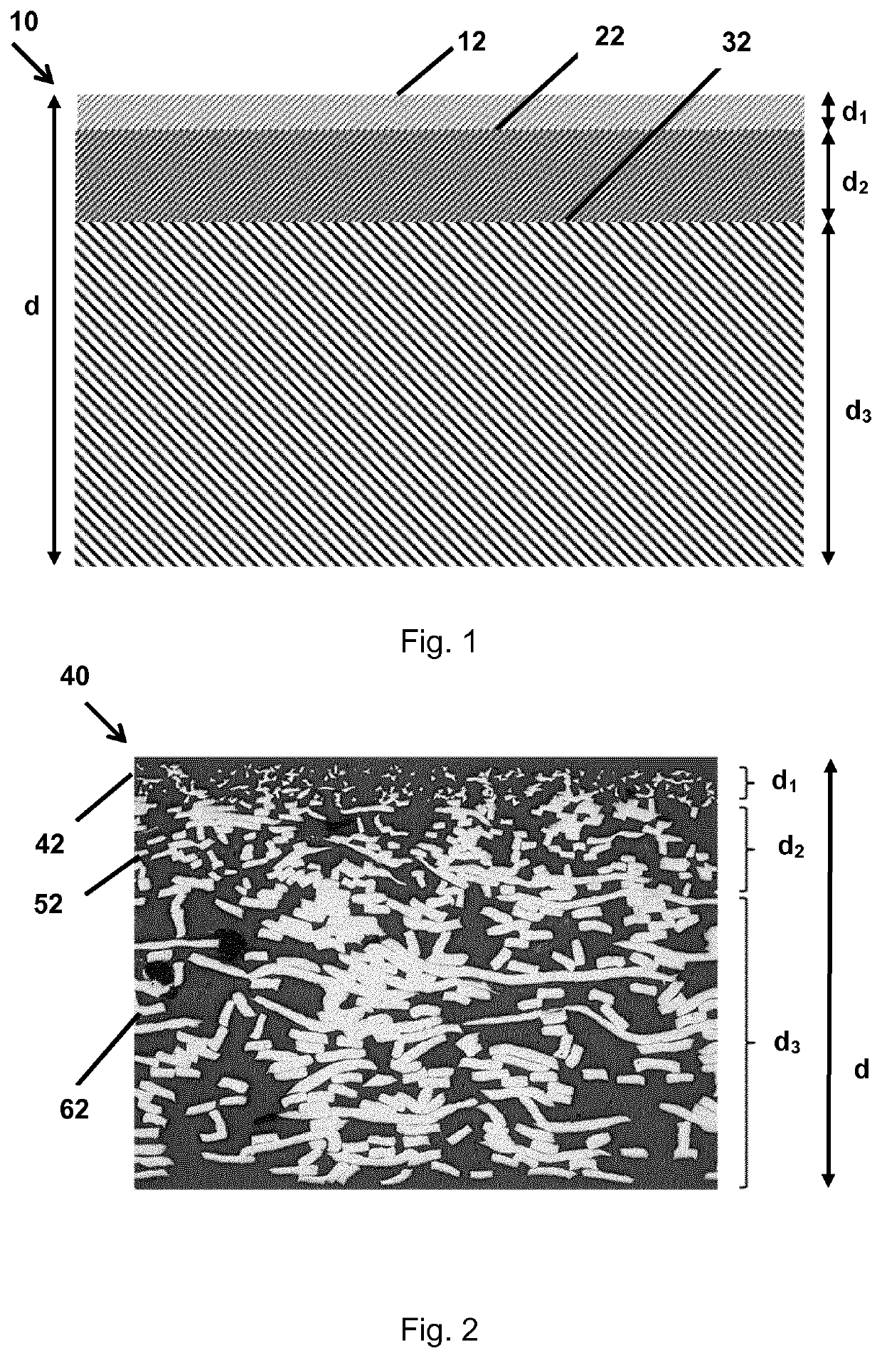
[0039]A first exemplary gas diffusion layer 10 according to the invention is schematically shown in FIG. 1. A magnified picture of the cross section of this first exemplary gas diffusion layer 40 is shown in FIG. 2. The first exemplary gas diffusion layer 10, 40 consists out of a first nonwoven layer 12, 42 of titanium fibers, a second nonwoven layer 22, 52 of titanium fibers and a third nonwoven layer 32, 62 of titanium fibers. The first nonwoven layer of titanium fibers is provided for contacting a proton exchange membrane in an electrolyser. The first nonwoven layer of titanium fibers comprises titanium fibers of 22 μm equivalent diameter. The titanium fibers of the first nonwoven layer have 14 mm length; and have a cross section, wherein the cross section has two neighbouring straight lined sides with an included angle of less than 90 degrees and one or more irregularly shaped curved sides. The first nonwoven layer has a specific mass of 250 g / m2 and a thickness d1 0.11 mm.

[0040...


PUM

PropertyMeasurementUnit
equivalent diameteraaaaaaaaaa
thicknessaaaaaaaaaa
included angleaaaaaaaaaa

Abstract

A gas diffusion layer for an electrolyser or for a fuel cell comprises a first nonwoven layer of metal fibers provided for contacting a proton exchange membrane, a second nonwoven layer of metal fibers, and a third porous metal layer. The first nonwoven layer of metal fibers comprises metal fibers of a first equivalent diameter. The second nonwoven layer of metal fibers comprises metal fibers of a second equivalent diameter. The second equivalent diameter is larger than the first equivalent diameter. The third porous metal layer comprises open pores. The open pores of the third porous metal layer are larger than the open pores of the second nonwoven layer of metal fibers. The second nonwoven layer is provided in between and contacting the first nonwoven layer and the third porous metal layer. The second nonwoven layer is metallurgically bonded to the first nonwoven layer and to the third porous metal layer. The thickness of the third porous metal layer is at least two times—and preferably at least three times—the thickness of the first nonwoven layer.

Description

TECHNICAL FIELD[0001]The invention relates to the field of gas diffusion layers as are e.g. used in electrolysers and fuel cells.BACKGROUND ART[0002]WO03 / 059556A2 discloses a stack for use in a fuel cell or in an electrolyser. The stack comprises an impermeable metal structure, a first metal fiber layer and a second metal fiber layer. The impermeable metal structure is sintered to one side of the first metal fibers layer and the second metal fibers layer is sintered to the other side of the first metal fibers layer. The second metal fiber layer is provided as contact layer to a PEM (proton exchange membrane) in a fuel cell or in an electrolyser. The planar air permeability of the stack is more than 0.02 l / min*cm.DISCLOSURE OF INVENTION[0003]The first aspect of the invention is a gas diffusion layer for an electrolyser or for a fuel cell. The gas diffusion layer comprises a first nonwoven layer of metal fibers provided for contacting a proton exchange membrane (which could be coated ...

Claims


Application Information

Patent Timeline
Patent Type & Authority Applications(United States)
IPC IPC(8): H01M4/88H01M4/86
CPCH01M4/8807H01M4/8631H01M4/8621H01M4/861H01M2004/8694H01M4/8626Y02E60/50
Inventor DE BRUYCKER, RUBENGOOSSENS, DAVYSYNHAEVE, KRISDE BAERDEMAEKER, JEREMIE
Owner NV BEKAERT SA
Learn More