Ceramic matrix composite and method of manufacturing the same

a ceramic matrix and composite technology, applied in the field of ceramic matrix composites, can solve the problems of unreacted carbon powder likely to remain in the matrix, and achieve the effect of improving the oxidation resistance of the ceramic matrix composi

Active Publication Date: 2020-01-23
IHI CORP
View PDF0 Cites 4 Cited by
  • Summary
  • Abstract
  • Description
  • Claims
  • Application Information

AI Technical Summary

Benefits of technology

[0014]The foregoing configuration makes the matrix of the ceramic matrix composite contain no elem

Problems solved by technology

However, in the case where the matrix is formed by the carbon powder infiltration, the subsequent molten silicon infiltration and

Method used


Image

  • Ceramic matrix composite and method of manufacturing the same
  • Ceramic matrix composite and method of manufacturing the same
  • Ceramic matrix composite and method of manufacturing the same

Examples


examples

[0066]A matrix formation test was performed on the ceramic matrix composite.

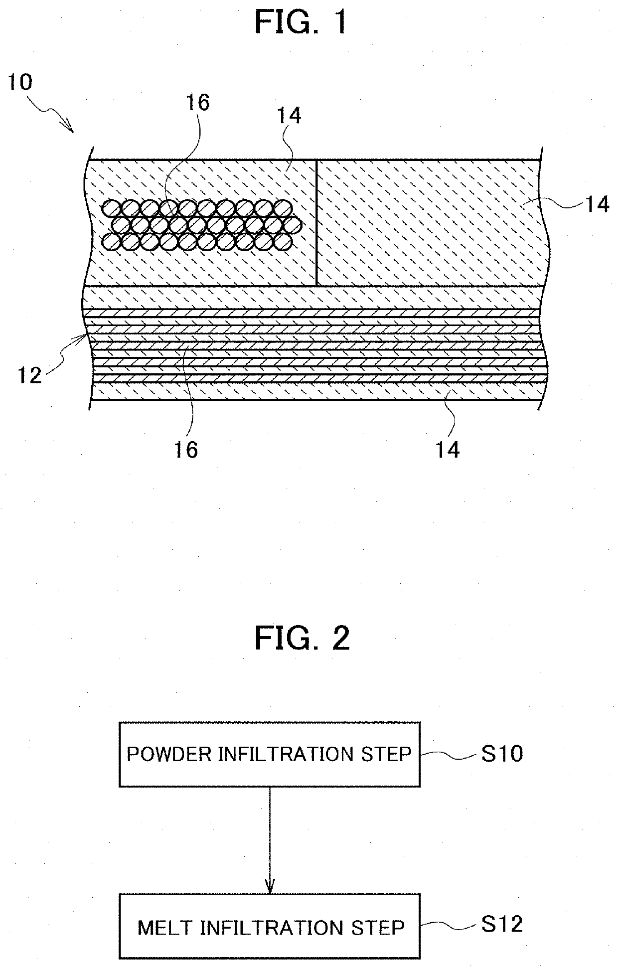
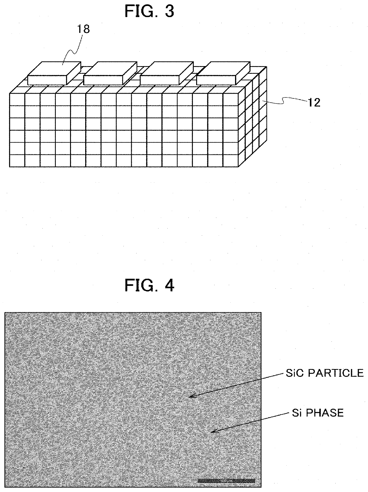
[0067]To begin with, descriptions will be provided for Example 1. Slurry was produced by mixing SiC powder containing no elemental carbon such as carbon powder with ethanol. SiC powder with an average particle diameter of 1 μm or more and 10 μm or less was used as the SiC powder. The slurry was poured into a rectangular mold, and was subsequently dried. Thereby, a rectangular SiC powder compact was formed.

[0068]Si was melted and infiltrated into the SiC powder compact. Ingots of Si were disposed on the SiC powder compact. The ingots were formed by arc melting. The SiC powder compact with the ingots disposed thereon was put into a thermal treatment furnace, and was thermally treated in the vacuum atmosphere at a thermal treatment temperature of 1450° C. for a holding time of 20 minutes. Through this thermal treatment, the ingots were melted, and Si was melted and infiltrated into the SiC powder compact. The s...


PUM

PropertyMeasurementUnit
Temperatureaaaaaaaaaa
Melting pointaaaaaaaaaa

Abstract

A ceramic matrix composite includes a substrate which contains a fibrous body made of silicon carbide fiber, and a matrix which is formed in the substrate, and which contains silicon carbide and a silicon material made of silicon or a binary silicon alloy.

Description

CROSS REFERENCE TO RELATED APPLICATIONS[0001]This application is a continuation application of International Application No. PCT / JP2017 / 015243, filed on Apr. 14, 2017, which claims priority to Japanese Patent Application No. 2016-164731, filed on Aug. 25, 2016, the entire contents of which are incorporated by references herein.BACKGROUND1. Field[0002]The present disclosure relates to a ceramic matrix composite and a method of manufacturing the same.2. Description of the Related Art[0003]As high-temperature materials for aircraft engines, and the like, ceramic matrix composites (CMCs) have drawn attention since the specific gravities of the ceramic matrix composites are equal to or less than one third of those of heat-resistant metal materials such as Ni alloys, and the ceramic matrix composites are excellent in heat resistance. Melt infiltration is one of ceramic matrix composite manufacturing methods, and forms a matrix by infiltrating molten silicon. Melt infiltration makes it pos...

Claims


Application Information

Patent Timeline
IPC IPC(8): C04B35/80C04B35/657C04B35/628
CPCC04B35/62863C04B2235/616C04B2235/40C04B2235/5244C04B2235/428C04B35/657C04B35/806C04B2235/3826C04B41/85C04B35/565C04B35/6316C04B35/62868C04B35/62884C04B2235/721C04B2235/5436C04B2235/3891C04B2235/96C04B2235/9684C04B35/80
Inventor SATO, AKIHIROKANAZAWA, SHINGONAGAMI, YUUYAKAKIUCHI, RYOJI
Owner IHI CORP
Why Eureka
Try Eureka