
Industrial system for energy storage

a technology of energy storage and industrial system, which is applied in the direction of dynamo-electric machines, motors, locomotives, etc., can solve the problems of deteriorating the quality of electrical energy supplied, difficult to maintain a balance between generated and consumed electric power, and inability of the electric power grid to store electric energy, etc., to facilitate the vertical movement of the carriage

Active Publication Date: 2020-02-06
LLC ENERGOZAPAS
View PDF0 Cites 8 Cited by
  • Summary
  • Abstract
  • Description
  • Claims
  • Application Information

AI Technical Summary

Benefits of technology

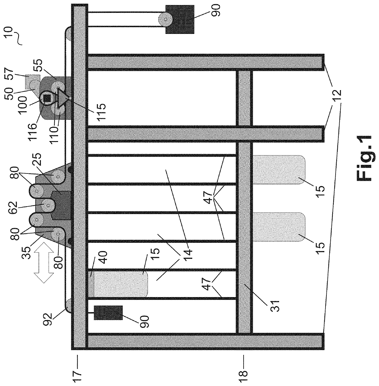
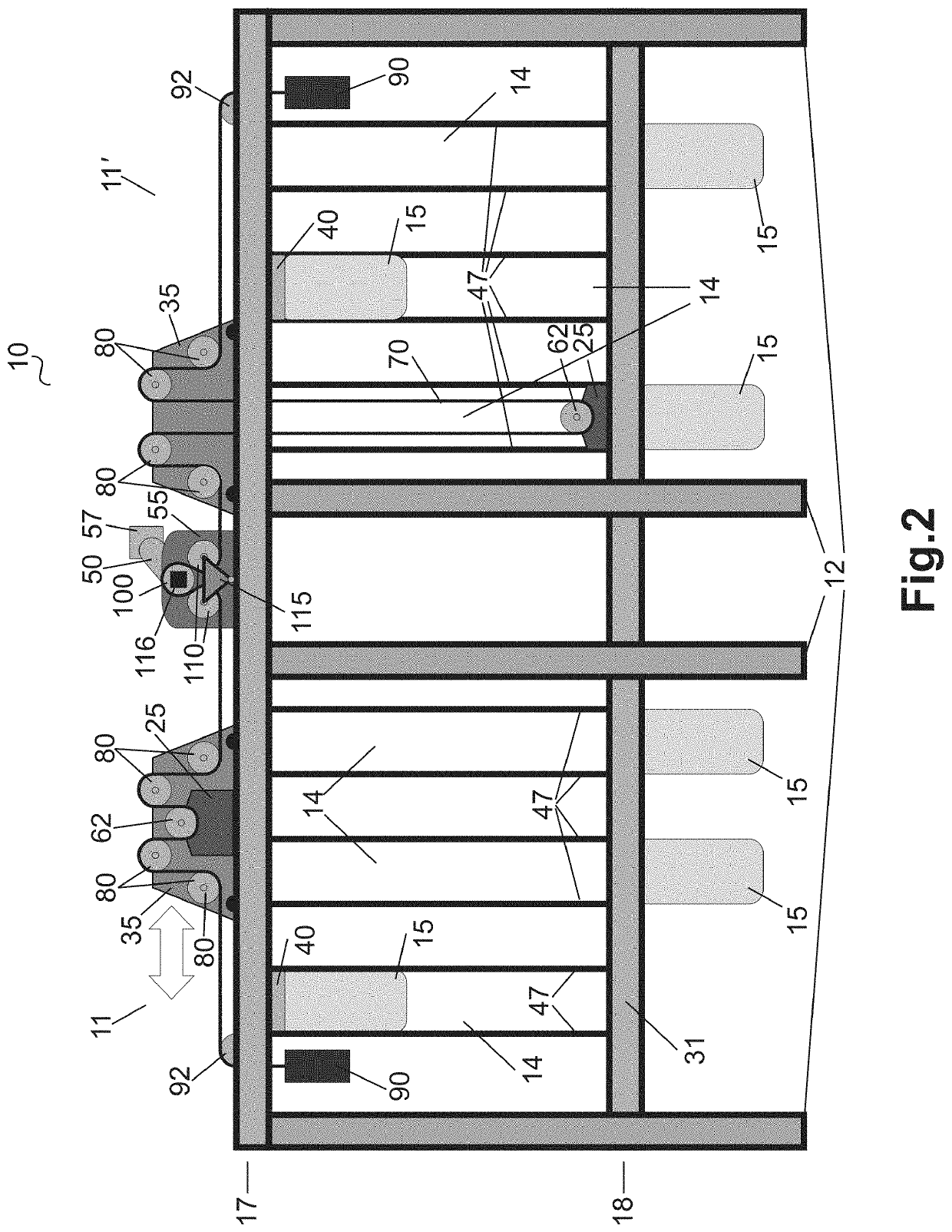
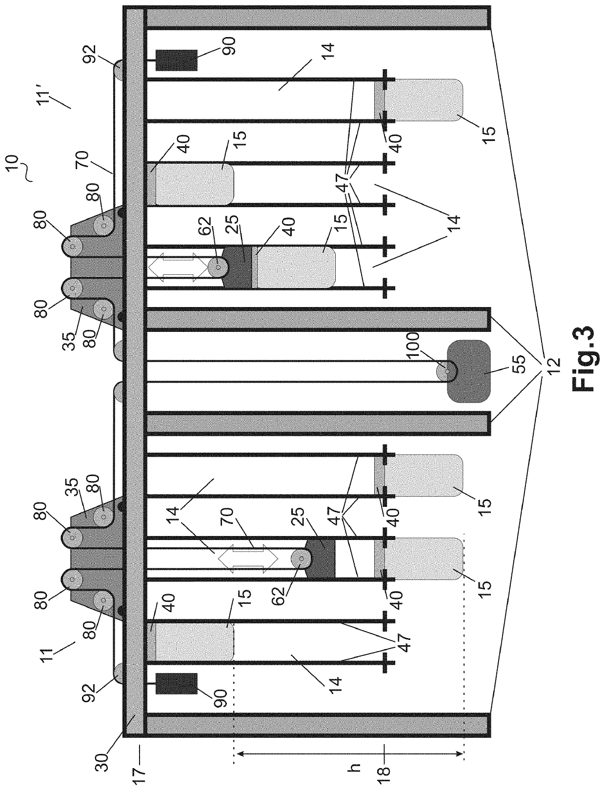
The energy cell is designed to carry and move weights vertically and horizontally within a structure. The carriage is responsible for vertical movement and the trolley is responsible for horizontal movement. The carriage and trolley are connected by a belt with two tensioners, and the main drive controls both vertical and horizontal movement. The trolley needs a separate energy source to move horizontally, while the carriage can move vertically with or without the weights. This design allows for more efficient and controlled movement of the weights within the energy cell.

Problems solved by technology

It is well known that the electric power grid is not able to store electric energy without the use of an energy storage system.
Accordingly, the difficult task of maintaining a balance between generated and consumed electric power exists in the large power systems.
The imbalance between the generated and consumed power leads to deterioration of the quality of the electrical energy supplied.
For example, the imbalance between the generated and consumed power can cause changes in the frequency or / and voltage of the alternating current, which can lead to serious failures of the power system equipment.
However, the use of the maneuverable power plants is generally limited.
Capital cost of other maneuverable power plants significantly exceeds capital cost of the similar constant power plants, and efficiency remarkably drops when exiting the constant power mode.
Moreover, continued use of the power plants at the variable capacity usually causes premature deterioration of the equipment.
This issue for addressing the imbalance is becoming more complicated with the expansion of use of alternative (e.g. renewable) energy sources, such as wind power and solar power plants that have inherent issues with consistency of power production because the production depends on unpredictable and uncontrollable environmental conditions.
If renewable energy source (RES), whether it is solar or wind power, is used in an isolated electric grid without an energy storage system it is accidental that at any given moment RES' power production correlates with its consumption.
Accordingly, in most cases this is not the case, and results in discharge of excess electrical power or in power surges, which greatly affect the efficiency of the power system.
As a rule, energy producers use the equipment with knowingly surplus capacity relatively to the actual energy demand to provide the electric grid with the amount of energy precisely matching the instantaneous demand to guarantee spare energy by increasing capital and operating costs.
This method proved effective in comparison to traditional power plants, however, in case of RES, it does not guarantee the required amount of energy in the event of unfavorable weather conditions.
The energy intensity of the PHS is linearly dependent on the volume of water body, which ultimately leads to a requirement of a large area of land being available for construction.
The operation of the plant is also associated with a number of risks, among them the main ones are a possibility of large-scale damage in the event of an accident and a negative impact on the environment.
This is because the use of artificial reservoirs leads to an increase in capital costs and a reduced economic competitiveness.
An important disadvantages of industrial storage devices that use lithium-ion batteries is a combination of relatively low durability with high capital costs, which ultimately leads to the problem of cost-effectiveness.
High capital costs for industrial lithium-ion batteries drives the need to achieve the required power by using a large number of low-power cells.
Further, the surface of the battery increases with increasing power more slowly than the generated by the battery heat, which leads to a decrease in efficiency.
Thus, the possibility of using large lithium-ion cells is limited by the efficiency.
Finally, due to the rise in prices for raw lithium, the prospects for the use of the lithium-ion battery storage devices on an industrial scale are controversial.
The weight of the cargo puts extremely high demands on the strength characteristics of the mechanical assemblies of such systems, as well as the demands for safety precautions.
This system employs a block and tackle with the high number of rope loops in order to reduce the lifting force, thereby resulting in a significant reduction in the system efficiency.
Structure of other systems results in substantial reduction of efficiency and significant damage in case of an emergency.

Method used


Image

  • Industrial system for energy storage
  • Industrial system for energy storage
  • Industrial system for energy storage

Examples


Embodiment Construction

[0053]Aspects of the invention are disclosed in the following description and related drawings directed to specific embodiments of the invention. Alternate embodiments may be devised without departing from the scope of the invention. Additionally, well-known elements of the invention will not be described in detail or will be omitted so as not to obscure the relevant details of the invention.

[0054]The word “exemplary” is used herein to mean “serving as an example, instance, or illustration.” Any embodiment described herein as “exemplary” is not necessarily to be construed as preferred or advantageous over other embodiments. Likewise, the term “embodiments of the invention” does not require that all embodiments of the invention include the discussed feature, advantage or mode of operation.

[0055]The terminology used herein is for the purpose of describing particular embodiments only and is not intended to be limiting of embodiments of the invention. As used herein, the singular forms ...


PUM


Abstract

The present disclosure is directed to a system for electric energy storage. The system includes at least one energy cell. The energy cell has a plurality of weights, a carriage, a trolley, a belt and a main drive. The system is configured to move vertically the weights and to store the weights on either an upper portion or a lower portion of the energy cell. The system is charged or discharged by moving the weights from the lower portion to the upper portion or from the upper portion to the lower portion. The present disclosure also provides for a method for electric energy storage.

Description

BACKGROUND OF THE INVENTIONField of the Invention[0001]The present disclosure relates to an electric energy storage. In particular, the present invention provides an industrial system for electric energy storage by employing vertical movement of weights.Description of the Background Art[0002]It is well known that the electric power grid is not able to store electric energy without the use of an energy storage system. The modern electric power systems are increasingly complex and the matching of power generation supply with power usage is a critical element in maintaining stability in operation of the systems.[0003]The demand for electricity generation over a typical twenty-four hour period changes significantly due to the differences in electricity consumption. For example, a common scenario that during morning and evening hours the consumption of electricity is increased (peak hours) and during night hours the consumption is minimal (off-peak hours). Accordingly, the difficult task...

Claims


Application Information

Patent Timeline
Patent Type & Authority Applications(United States)
IPC IPC(8): H02J15/00B61C17/06H02K7/18B60L55/00B61C3/00
CPCB60L2200/30B60L55/00B61C17/06H02J15/00H02K7/1807B61C3/00F03G7/08F03G3/00H02J15/007Y02T30/00F03G3/094
Inventor SOLOBOEV, SERGEY VLADIMIROVICHBRYZGALOV, ANDREY ANDREEVICH
Owner LLC ENERGOZAPAS
Learn More