Diaphragm Valve Structure

a diaphragm valve and structure technology, applied in the direction of diaphragm valves, engine diaphragms, valve housings, etc., can solve the problems of diaphragm leakage, high corrosive environment, diaphragm valves, etc., to improve dependability and durability, high structural strength, and high corrosive environment

Active Publication Date: 2020-03-05
BUENO TECH
View PDF0 Cites 7 Cited by
  • Summary
  • Abstract
  • Description
  • Claims
  • Application Information

AI Technical Summary

Benefits of technology

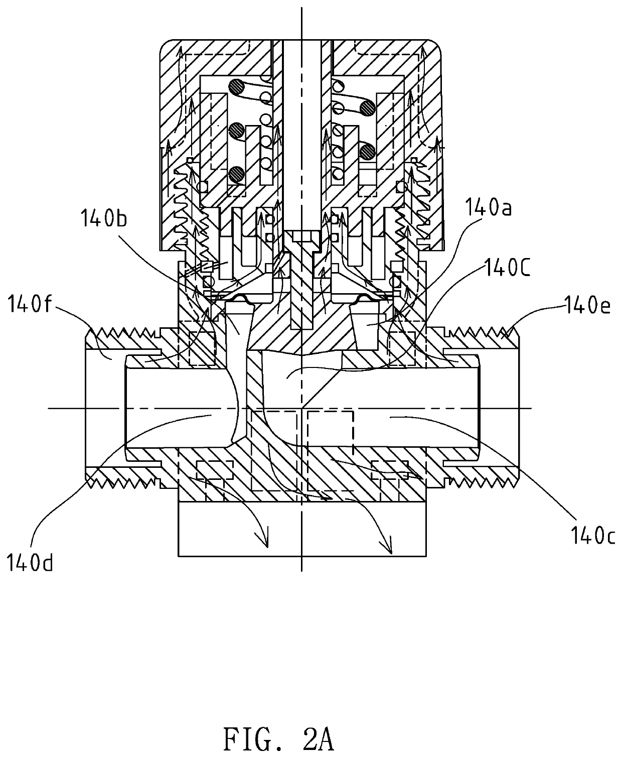
[0115]During forced circulation cooling, high pressure coolant gas passes through a coolant gas connection as the supply entry point to enable improving dependability and durability for application at temperatures reaching as high as 200° C. and in a high corrosive environment. Problem 4: Tightening and sealing. The valve body and the gas cylinder structure and the structure of the valve shaft set meet the requirements to provide high structural strength, resistance to surrounding corrosive gas, and endurance to the reciprocating motion of the piston.
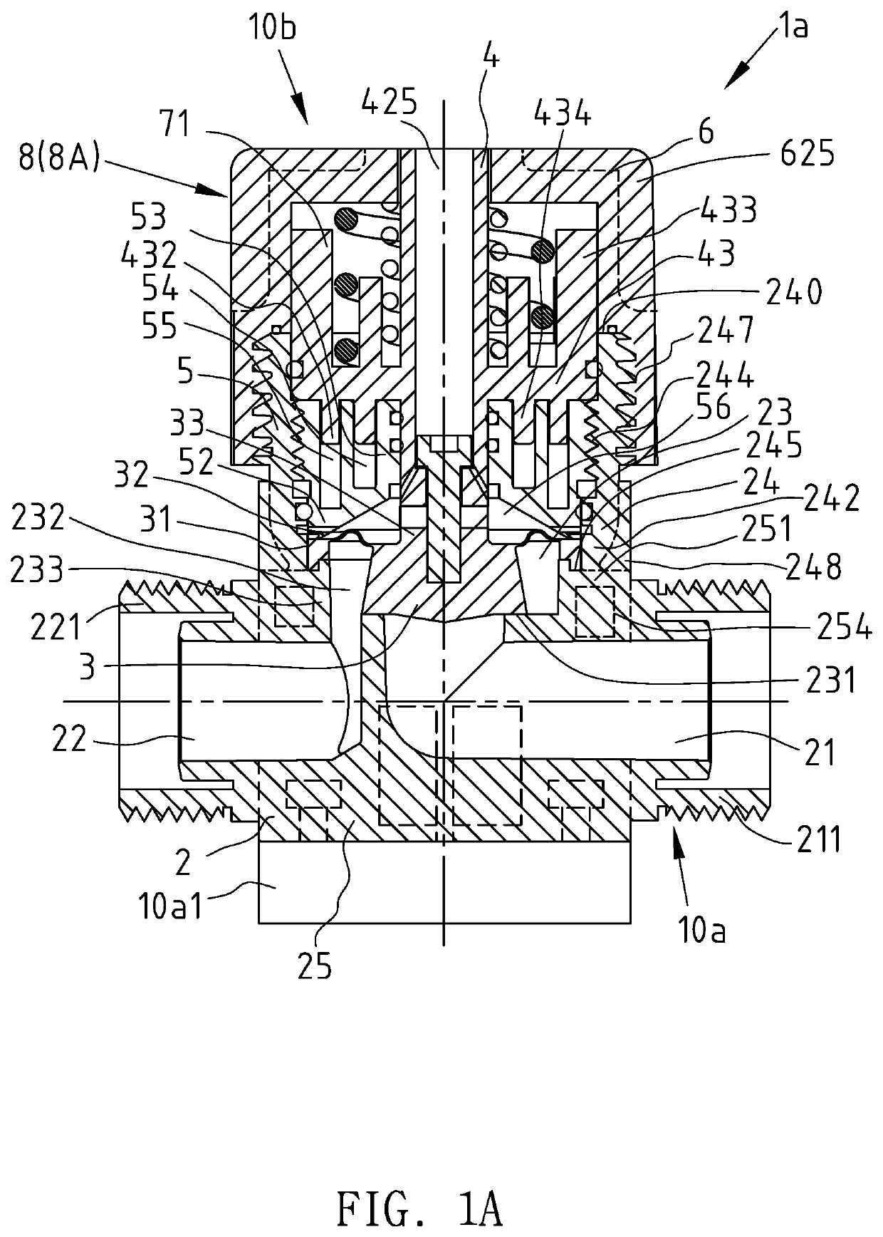
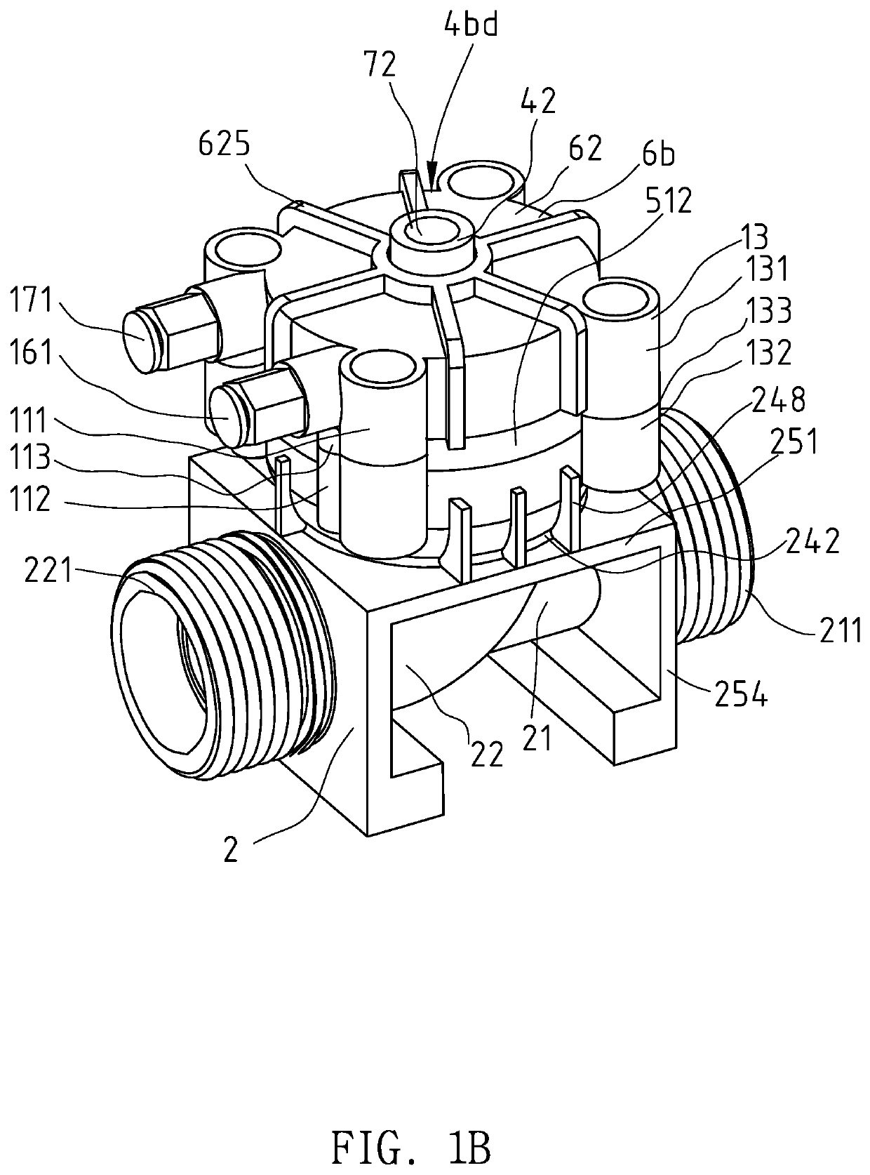
[0116]Regarding the high structural strength, the square portion of the valve is provided with the lattice-shaped ribbed structure with horizontal openings, which provide the structural strength and heat transfer restriction. The annular portion and the valve box construct the cup-shaped structure, which assumes a deep cup shape because the height range of the outer edge reaches 80% to 160% of the height of the upper valve body, moreover, the diaphragm is assembled at a position close to the bottom portion of the cup-shaped structure, wherein this position is also provided with the coolant flow channel to effect cooling, thus, under conditions of high temperature distortion, the annular portion assists in providing high structural strength that is stronger compared to the prior art. The valve shaft set is assembled on the annular portion, that is, the deep cup-shaped structure provides the valve shaft set with the most stable structural support. Hence, concentricity and perpendicularity is ensured when the valve shaft is performing an opening / closing movement, and maximum assistance to reducing particle release is provided. The gas cylinder structure is supported by the structure of the annular portion, ensuring rigid support of the shaft hole portion and ensuring perpendicularity and concentricity of the valve shaft. The external ring surface fitted with heat dissipation ribbed plates provides an additional supporting force for the gas cylinder. The piston transfers the actuation gas pressure and spring vibrations of the gas cylinder to the valve body, the structure of which absorbs and endures, thereby substantially reducing structural loosening resulting from the tightening force producing structural creeping. Moreover, the gas cylinder structure is positioned above the heat transfer restriction areas of the annular portion, and the upper valve body is provided with the heat transfer restriction areas, which are able to minimize heat transmission of the heat source areas and maintain strength of the gas cylinder structure.
[0117]Regarding resistance to surrounding corrosive gas, when using a non-metallic structure, the valve upper cover is tightly screwed onto the valve body using threaded teeth, thus removing contamination problems from metallic oxides. When using a metallic structure, the metal bolts of the gas cylinder structure are protected by the bolt sleeves; moreover, only one sealing face has the bolt sleeves, and the height difference value between the sealing face and the peripheral portion of the diaphragm at least equals to more than 80% of the length of the upper valve body. When metallic oxides are diffusing everywhere, such a height difference is sufficient to isolate the contamination permeating problem, and eliminates the need for operators and inspectors to inspect whether or not the bolts are corroded and need replacing, that is, even though the external surface of the valve body is subjected to corrosion by the surrounding corrosive gas, the problem of reduction in the tightening force will not occur.
[0118]Regarding endurance to the reciprocating motion of the piston, reciprocating motion of the piston takes place in the gas chamber, and the upper valve body is assembled on the internal ring surface of the annular portion; moreover, the valve body bears the acting force from multiple movements of the piston, therefore, the upper valve body will not distort and loosen. Further, the tightening force will not reduce causing in leakage from the diaphragm, thereby ensuring concentricity and perpendicularity of the valve shaft, and maintaining the tightening force on the peripheral portion of the diaphragm to minimize leakage and extend the serviceable life thereof.

Problems solved by technology

Nonetheless, in actual practice, a metal ball valve with a fluororesin inner lining can also be used at a high temperature of 200° C. and in a high corrosive environment, clearly revealing that requiring a diaphragm valve made completely from fluororesin in an operating environment at a high temperature of 200° C. and in a high corrosive environment is still a huge challenge.
When the piston is performing up and down reciprocating motion in the gas chamber, the upper valve body must sustain multiple vibrations and considerable gas chamber stress, which easily cause bending of the valve shaft, resulting in the diaphragm leaking.
Positions of the lower bolt sleeves of the second sealing face are close to the outer edge of the diaphragm, which also result in the worrying problem of two-way permeation contamination, meaning the manufacturing engineer needs to constantly pay attention to the corrosion condition of the metal bolts.
In other words, none of the diaphragm valves of the prior art can satisfy the requirements for application at an operating temperature of 200° C.
Diaphragm valve structures of the prior art guide and continue to accumulate heat inside the diaphragm valve, which causes the entire structure to be at a high temperature and reduces the temperature gradient; moreover, is unable to maintain structural strength.
Sealing components such as a fluororesin O-ring are unable to avoid the danger of high temperatures, and can only be used at an operating temperature less-than 160° C.
The external structure surface must have sufficient natural cooling, otherwise, it is unable to provide a sufficient heat dissipating capacity to maintain a temperature gradient and structural strength.
In addition. there is also the problems of the structures of the valve portion and the actuation gas cylinder having to sustain pressure and a reciprocating motion of the piston, including the problems of surrounding corrosive gas, all of which result in sealing failure.
However, when the structural strengths of the components themselves are inadequate then structural creeping occurs.
For example, when the thickness of the structures is too thin, high temperatures will result in structural distortion, which greatly reduces the tightening force of the bolts causing the diaphragm to leak.
In addition, the effect of vibration on the gas cylinder structure and the valve body will also result in structural creeping and distortion, which will reduce the tightening force of the bolts.
And reduction in the tightening force on the peripheral portion of the diaphragm will result in leakage.
Regarding corrosion by the surrounding gas, the four tightening bolts are protection of by bolt sleeves, however, high penetrability of corrosive gas will still intrude into the first sealing face and the second sealing face of the bolt sleeves, resulting in damage to the bolts and reducing the tightening force thereof.
In particular, the position of the second sealing face of the bolt sleeves is close to the outer edge of the diaphragm, which will greatly increase the risk of the bolts becoming eroded and the worrying problem of two-way permeation contamination.
Accordingly, with continued operation in an operating environment at a high temperature of 200° C., the diaphragm valve will inevitably encounter the above-described problems 1 to 4.
Reciprocating motion of the piston and the counteracting forces of springs produces vibration, and after a long period of operation, structural creeping and distortion will cause reduction in the degree of tightness in the structure.
Hence, numerous prior art technologies use springs or vibration damping rubber to reduce vibration to prevent leakage in the diaphragm; moreover, reducing vibration also decreases production of friction particles.
In addition, structural distortion of the valve body, upper valve body, and valve upper cover results in the valve shaft being unable to maintain concentricity and perpendicularity, and a frontal surface press connection cannot be effected between the diaphragm and the valve seat, causing friction therebetween and the production of friction particles.
The problem of an accumulation of static electricity in both the valve body and the diaphragm occurs when channeling nonconducting liquid; when the problem becomes serious, discharge sparks will damage the diaphragm.

Method used


Image

  • Diaphragm Valve Structure
  • Diaphragm Valve Structure
  • Diaphragm Valve Structure

Examples


reference example 2

[0049]The 1996 Japanese Patent No. JPH08152078 (A) discloses a gas-Operated Valve, which is provided with a linear magnetic structure able to detect opening of a diaphragm. The structure in this reference patent is suitable for applications at normal temperature but is unsuitable for applications at high temperatures. However, the exterior exposed pipe connections of the structure have no inlet connection heat source areas or outlet connection heat source areas; the structure has relatively small inlet pipe heat source areas and outlet pipe heat source areas. Compared to other prior art structures, the present reference patent has the characteristic of having heat source areas that are relatively small. However, the inlet pipe and outlet pipe still have large accumulated thickness areas, which form heat transfer channels that directly connect with the annular portion of the square plate. The upper valve body of the present reference example uses threaded teeth to tighten on the oute...

reference example 3

[0055]The 1997 Japanese Patent No. JPH09217845 (A) discloses a Diaphragm Valve, and describes a normally closed diaphragm valve structure attached with shock absorbing springs. The structure in this reference patent is suitable for applications at normal temperature but is unsuitable for applications at high temperatures. Normally closed springs are fitted on the upper side of the piston to ensure the diaphragm is able to press down on the valve seat. And secondary springs fitted on the lower side of the piston enable the diaphragm to smoothly close when closing, which substantially reduce the possibility of the valve seat producing friction particles. The reference example 3 is suitable for use in normal temperature applications, and apart from resolving problems 1 to 4, it also resolves the above-described problems 5 and 6. Descriptions of scenarios to resolve problems 1 to 6 are provided below:

[0056]Problem 1: Heat transfer restriction. The structure has large accumulated thickne...

reference example 4

[0062]The 2015 Chinese Patent No. CN104633171 (A) discloses a Valve Apparatus, the structure of which is suitable for applications at normal temperatures but is unsuitable for applications at high temperatures. The valve structure has conductive material installed in the valve shaft center, and the conductive material is able to contact channeling liquid to remove static electricity on the diaphragm. When the valve structure is channeling nonconducting high-purity water or other nonconducting liquid, the nonconducting diaphragm and valve body will accumulate frictional static electricity; and when the high voltage static electricity on the diaphragm is discharged to the upper valve body, the diaphragm will be punctured and damaged. The conductive material on the valve shaft is generally a heat conductor, which easily transmits heat from the valve box to other structures, and, thus, an imperfect heat source separation design.

[0063]The 2010 Japanese Patent No. JP2010121689 (A) disclos...


PUM


Abstract

A diaphragm valve structure having application in diaphragm valves made completely from fluororesin at an operating temperature of 200° C. The diaphragm valve uses a heat separation method that consists of a heat transfer limiting structure and a heat dissipating structure, ensuring rigidity of the gas cylinder structure. The heat transfer limiting structure uses lattice-shaped ribbed plates with horizontal openings, wherein the lattice-shaped ribbed plates and a minimum diameter area of an annular portion are all provided with heat transfer section thickness. The heat dissipating structure consists of a multilayered structure for a preferred external natural cooling, and further using a coolant gas ensuring that the peripheral portion of the diaphragm and gas-tight sealing components on the valve shaft are sufficiently cooled.

Description

CROSS REFERENCES TO RELATED APPLICATIONS[0001]The present application claims priority from Taiwanese Patent Application Serial Number 107131198, filed Sep. 5, 2018 the disclosure of which is hereby incorporated by reference herein in its entirety.BACKGROUND OF THE INVENTION(a) Field of the Invention[0002]The present invention relates to a diaphragm valve structure, and more particularly to a diaphragm valve made from fluororesin that achieves an extremely low heat transfer coefficient of approximately 0.25 W / (mK), which is far below that of ceramic aluminum oxide (Al2O3) that achieves a heat transfer coefficient of 30 W / (mK). Such an extremely low heat transfer characteristic enables the fluororesin material to withstand an operating environment at a high temperature of 250° C. However, the diaphragm valve must withstand high pressure, and currently only has application in a high corrosive environment at a high temperature less-than 160° C. In order to achieve the capability for app...

Claims


Application Information

Patent Timeline
Patent Type & Authority Applications(United States)
IPC IPC(8): F16K49/00F16K7/12
CPCF16K49/005F16K7/12F16K27/0236F16K31/1221F16K49/00F16K31/126F16K24/042
Inventor CHIEN, HUAN-JANCHEN, PO-WENHONG, HUAN-CIAO
Owner BUENO TECH
Why Eureka
Try Eureka