Amplifier device

Active Publication Date: 2020-03-05
INFINEON TECH AG
View PDF6 Cites 0 Cited by
  • Summary
  • Abstract
  • Description
  • Claims
  • Application Information

AI Technical Summary

Benefits of technology

[0034]Note that further embodiments herein include an improved multi-stage amplifier device and method to improve the “High Gain Mode” performance of a LNA circuit with matching im

Problems solved by technology

One drawback of the conventional amplifier in FIG. 1 is the voltage divider, namely, the combination of capacitor C1 and capacitor C2 in the output stage 130.
This transformation has a big drawback because it is possible to lose 25-50% of the voltage gain.
Unfortunately, the conventional output stage 130 of amplifier 100 only provides proper impedance matching in a very narrow frequency range such as 20 MegaHertz range.
This is very limiting because the amplifier 100 can

Method used


Image

  • Amplifier device
  • Amplifier device
  • Amplifier device

Examples


Embodiment Construction

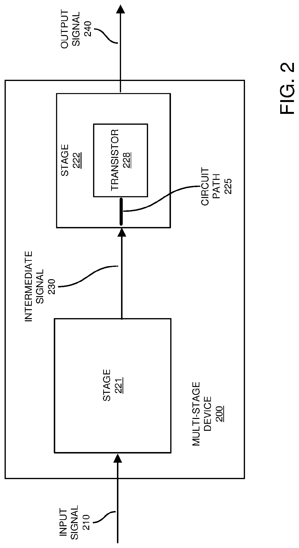
[0055]Embodiments herein include an apparatus amplifier comprising: a first stage to receive an input signal, the first stage producing an intermediate signal based on the input signal; and a second stage coupled to the first stage to receive the intermediate signal and produce an output signal. The second stage includes: i) a transistor, and ii) a circuit path between the first stage and the transistor. The intermediate signal is inputted to the circuit path to derive the output signal from the intermediate signal.

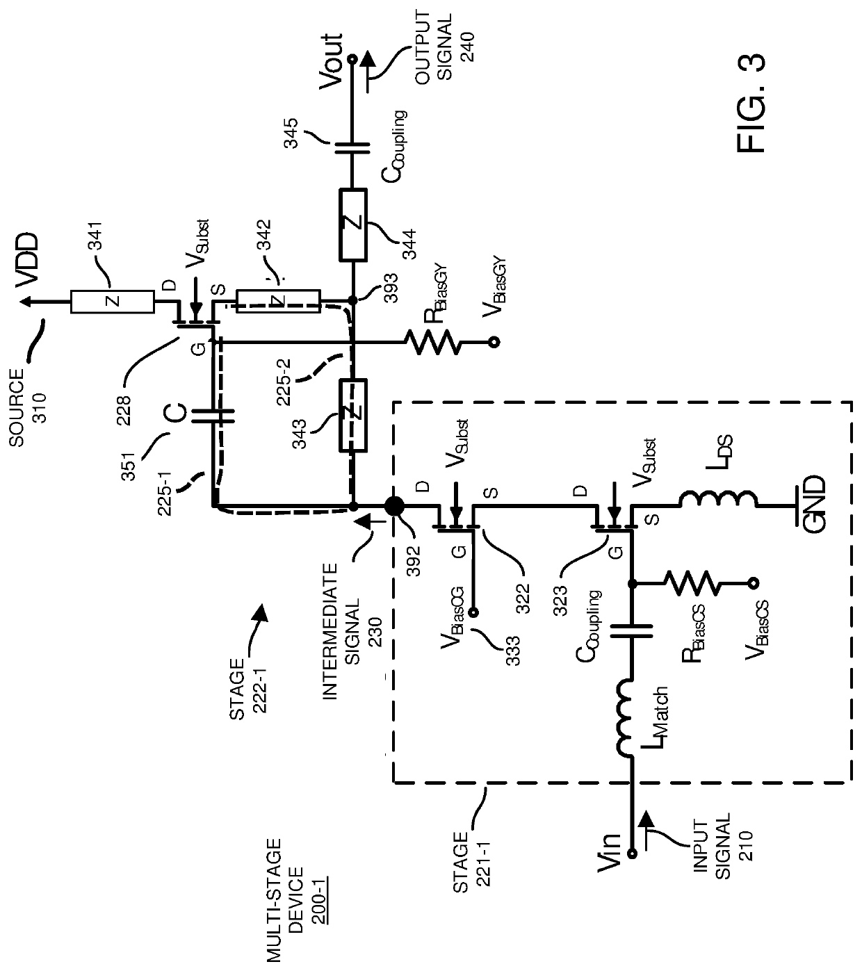
[0056]Now, more specifically, FIG. 2 is an example diagram illustrating a novel multi-stage device according to embodiments herein. By way of non-limiting example embodiment, the multi-stage device as described herein is a multi-stage amplifier device. For instance, the multi-stage device is a low-noise amplifier or so-called LNA device, apparatus, circuit, etc.

[0057]As shown, in this example embodiment, multi-stage device 200 includes any number of stages.

[0058]For examp...


PUM


Abstract

A multi-stage device includes multiple stages such as a first stage and a second stage. During operation, the first stage receives an input signal and outputs an intermediate signal based on the input signal. The second stage is coupled to the first stage to receive the intermediate signal and produce an output signal. According to one configuration, the second stage includes: i) a transistor, and ii) a circuit path between the first stage and the transistor. The transistor component is controlled to derive the output signal from the intermediate signal inputted to the circuit path.

Description

BACKGROUND[0001]A conventional Low-Noise Amplifier (LNA) is an electronic amplifier that amplifies a very low-voltage input signal into an output signal without significantly degrading its signal-to-noise ratio. As a specific example, depending on a respective gain setting, an amplifier circuit produces a higher magnitude replica of the input signal, preferably with limited noise amplification.[0002]Conventional LNA circuitry used in mobile communication devices typically support a so-called “linearity on demand” feature, which requires the implementation of different gain step modes. One of these modes is the so-called “High Gain Mode”, which uses the maximum allowed current to achieve best gain and noise figure performance from the input to the output. Proper operation and performance of a communication device typically depends on the ability of the amplifier circuit to provide appropriate gain.[0003]FIG. 1 is an example diagram illustrating a conventional amplifier circuit operat...

Claims


Application Information

Patent Timeline
IPC IPC(8): H03F1/02H03F1/56H03F1/22H04B1/18
CPCH03F1/223H04B1/18H03F1/0216H03F2200/294H03F1/565H03H7/38H03F3/189H03G3/3036H03F3/193H03F3/211H03F3/505H03F2200/151H03F2200/411H03F2200/451H03F2200/492H03F2203/5015H03F1/56
Inventor SCHROEGENDORFER, DANIEL
Owner INFINEON TECH AG
Why Eureka
Try Eureka