
Integrated process-structure-property modeling frameworks and methods for design optimization and/or performance prediction of material systems and applications of same

Pending Publication Date: 2020-03-19
NORTHWESTERN UNIV
View PDF2 Cites 40 Cited by
  • Summary
  • Abstract
  • Description
  • Claims
  • Application Information

AI Technical Summary

Benefits of technology

The invention is a framework for design optimization and performance prediction of material systems. It includes a database, models for powder spreading and melting, and models for predicting stress-strain responses and fatigue life. The framework allows for the exchange of geometry information between the models, which helps to predict the behavior of materials under various conditions. The method involves generating a particle packing configuration, predicting a temperature profile, and writing the temperature profile to the database. The models are then used to predict grain information, which is used to identify the dense material and voids in the material. The method can be used to optimize the design of materials and predict their performance under various conditions.

Problems solved by technology

This flexibility is achieved in part because the process is highly localized; however, these processes lack reproducibility and reliability: the quality of the parts produced are sensitive to build conditions.
To overcome the challenges this poses in the production of functional, load-bearing or otherwise practically useful components, significant effort has been expended.
While great strides have been made, some core challenges still face multiscale methods, including accurate methods for homogenizing the microstructural representative volume element (RVE) undergoing strain localization, computation of strain localization with variable-sized microstructural features, and the ability to conduct efficient concurrent simulations.
Therefore, a heretofore unaddressed need exists in the art to address the aforementioned deficiencies and inadequacies.

Method used


Image

  • Integrated process-structure-property modeling frameworks and methods for design optimization and/or performance prediction of material systems and applications of same
  • Integrated process-structure-property modeling frameworks and methods for design optimization and/or performance prediction of material systems and applications of same
  • Integrated process-structure-property modeling frameworks and methods for design optimization and/or performance prediction of material systems and applications of same

Examples


example 1

Integrated Process-Structure-Property Modeling Framework for Additive Manufacturing

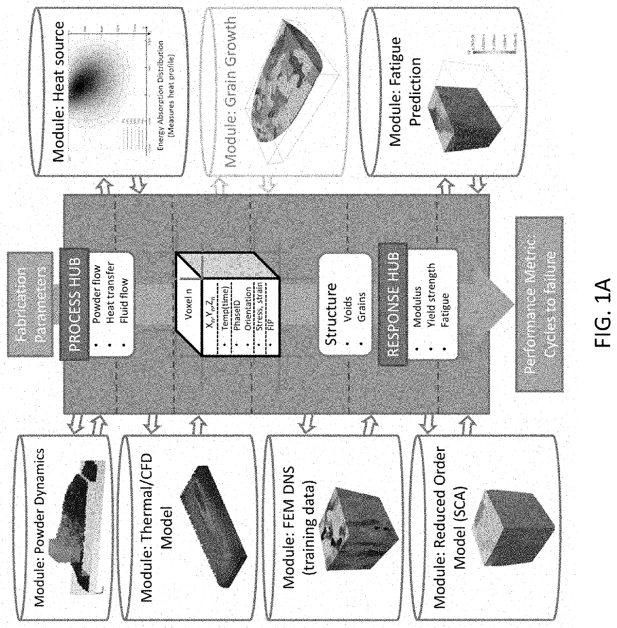
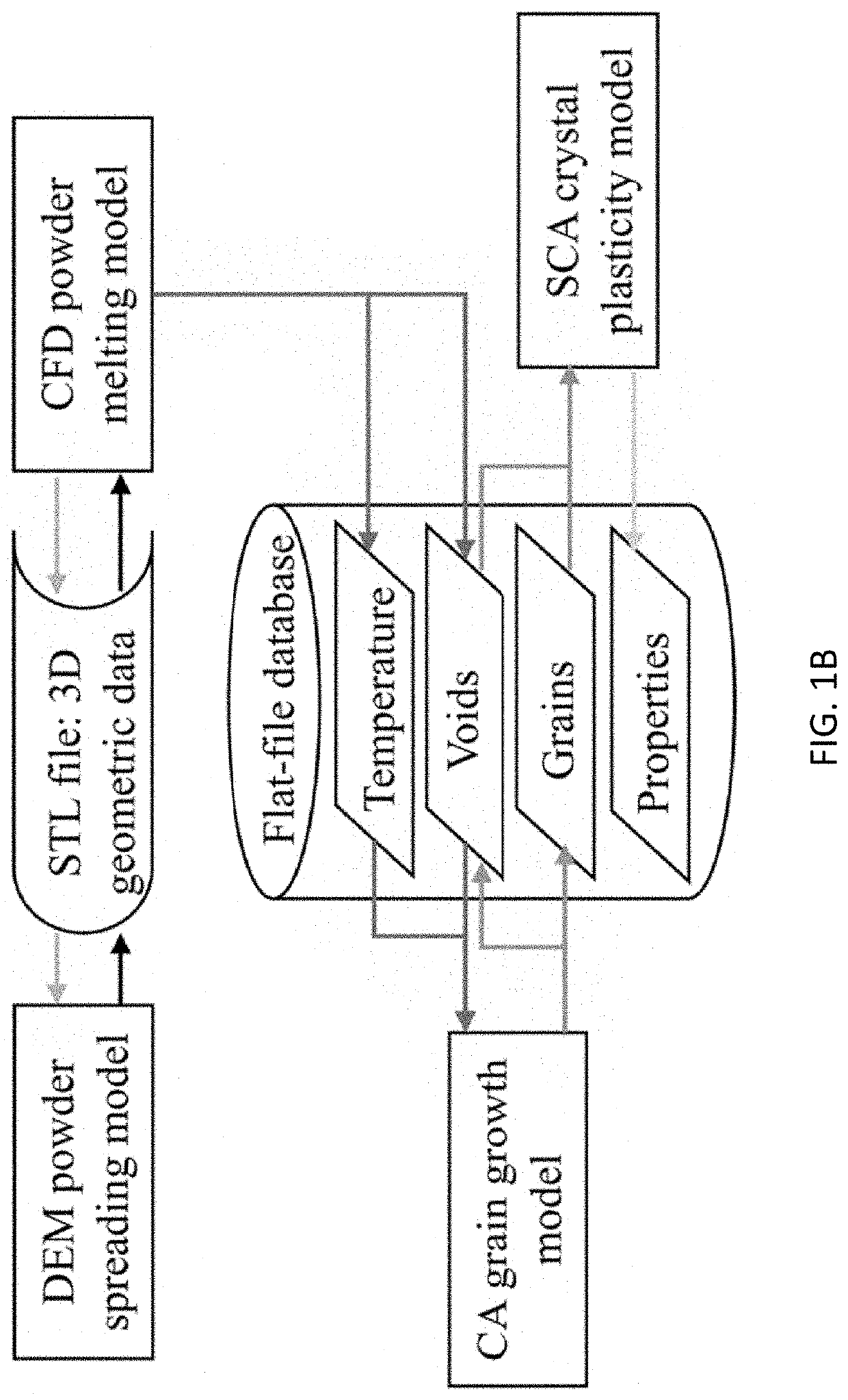
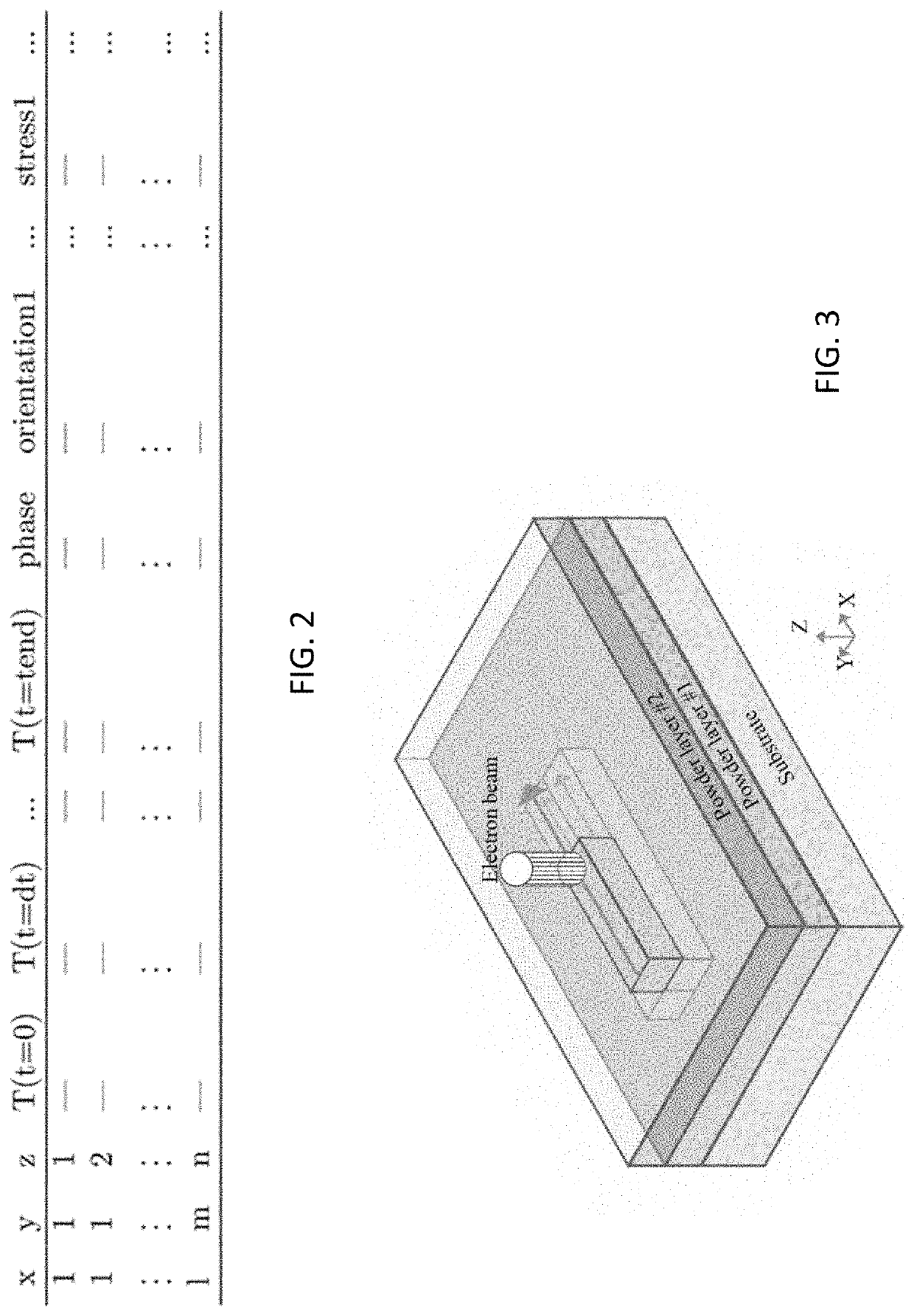
[0149]One objective of modeling for Additive Manufacturing (AM) is to predict the resultant mechanical properties from given manufacturing parameters and intrinsic material properties, thereby reducing uncertainty in the material built. This can dramatically reduce the time and cost for the development of new products using AM. In this exemplary study, we realize the seamless linking of models for the manufacturing process, material structure formation, and mechanical response through an integrated multi-physics modeling framework. The sequentially coupled modeling framework relies on the concept that the results from each model used in the framework are contained in space-filling volume elements using a prescribed structure. The implementation of the framework demonstrated herein includes: (1) a powder spreading model using the discrete element method (DEM) to generate the powder bed and a thermal-fl...

example results

and Discussion

[0189]The final result of this integrated framework is the computed performance metric. Here we also present intermediate results from each of the models described above, to make the flow of information between modules and hubs within the framework much clearer by example. Each of the modules contains a state-of-the-art method in itself; the important point that we demonstrate, to our knowledge for the first time in the open literature, is that the modules used to predict processing and material response to mechanical loading during service have been directly linked. A comparison of the final metric for build quality between cases with different processing conditions is made. The examples here show the influence of process parameter choices on simulated performance with two distinct cases shown in Table 1-3: one with hatch spacing 200 μm and the other with hatch spacing 240 μm. This allows us to directly show the differences in that result from different process parame...

example 2

Implementation and Application of the Multiresolution Continuum Theory

[0211]The multiresolution continuum theory (MCT) is implemented in FEA with a bespoke user defined element and materials. In this exemplary study, we focus on the formulation and implementation of the MCT model. A simple dog-bone model is used to validate the code and study the effect of microscale parameters. The ability of the MCT method to simulate the propagation of a shear band in simple shear geometry is shown. The length scale parameter is demonstrated to influence shear band width. Finally, we present a simulation of serrated chip formation in metal cutting, a case where accurate prediction of shear band formation is critical. The advantages of the MCT over conventional methods are discussed. This work helps elucidate the role of the length scale and microscale parameters in the MCT, and is a demonstration of a practical engineering application of the method: the simulation of high speed metal cutting (HSM...


PUM


Abstract

Integrated process-structure-property modeling framework and method for design optimization and / or performance prediction of a material system are provided. The Integrated process-structure-property modeling framework includes a powder spreading model using a discrete element method to generate a powder bed; a thermal-fluid flow model of the powder melting process to predict voids and temperature profile; a cellular automaton model to simulate grain growth based on the temperature profile; and a reduced-order micromechanics model to predict mechanical properties and fatigue resistance of resultant structures by resolving the voids and grains.

Description

CROSS-REFERENCE TO RELATED PATENT APPLICATION[0001]This application claims priority to and the benefit of, pursuant to 35 U.S.C. § 119(e), of U.S. provisional patent application Ser. No. 62 / 731,381, filed Sep. 14, 2018, entitled “MULTISCALE MODELING PLATFORM AND APPLICATIONS OF SAME”, by Wing Kam Liu, Jiaying Gao, Cheng Yu and Orion L. Kafka, which is incorporated herein by reference in its entirety.[0002]This application is related to a co-pending PCT patent application, entitled “DATA-DRIVEN REPRESENTATION AND CLUSTERING DISCRETIZATION METHOD AND SYSTEM FOR DESIGN OPTIMIZATION AND / OR PERFORMANCE PREDICTION OF MATERIAL SYSTEMS AND APPLICATIONS OF SAME”, by Wing Kam Liu, Jiaying Gao, Cheng Yu, and Orion L. Kafka, with Attorney Docket No. 0116936.152WO2, filed on the same day that this application is filed, and with the same assignee as that of this application, which is incorporated herein by reference in its entirety.FIELD OF THE INVENTION[0003]The invention relates generally to ma...

Claims


Application Information

Patent Timeline
IPC IPC(8): G06F17/50G06T17/20
CPCG06F2119/08G06T17/20G06F30/23G06F2111/10G06F2113/10B33Y50/00G06F30/27
Inventor LIU, WING KAMGAO, JIAYINGYU, CHENGKAFKA, ORION L.
Owner NORTHWESTERN UNIV
Learn More