MEMS Electrothermal Actuator for Large Angle Beamsteering

a technology of electrothermal actuators and beamsteering, which is applied in the direction of instruments, optical elements, coatings, etc., can solve the problems of increasing fuel consumption, minimal power, and inefficiency of the platform, and achieves high scanning speed, large beamsteering angles, and high fill-factor

Active Publication Date: 2020-03-26
THE UNITED STATES OF AMERICA AS REPRESETNED BY THE SEC OF THE AIR FORCE
View PDF0 Cites 5 Cited by
  • Summary
  • Abstract
  • Description
  • Claims
  • Application Information

AI Technical Summary

Benefits of technology

[0007]Embodiments of the invention address the need in the art by enabling new and improved beamsteering systems with large beamsteering angles, high scanning speeds, while exhibiting high fill-factor (>90%) arrays which are scalable to large aperture sizes as well as enabling a multi-beam scanning capability at low voltage. These embodiments may replace many gimbal based systems in a variety of applications since the device is nearly conformal, and it can eliminate nearly all large, moving mechanical parts of the scanning / detector system. Embodiments of the invention may be applicable to EO / IR beamsteering systems, medical endoscopy, imaging and scene generation systems, laser communications, and multi-target search and track. Embodiments of the invention use MEMS to enable the large angle beamsteering, scalable with regard to array size, flexible with regards to material selection, wavelengths of interest, and deflection / steering angles while being ideal for wideband applications.

Problems solved by technology

Although many of these research efforts exhibit large tip / tilt angles, they generally do not include a piston motion for optical correction requirements or exhibit high fill-factors for large area optical scanning applications.
Contemporary electrothermal designs have a maximum tip or tilt of ±30° for a single element but generally do not possess both capabilities.
These protrusions create significant drag resulting in the inefficiency of the platform and increase fuel usage.
These devices may also be critical elements in UAV applications since they are extremely small, lightweight and consume minimal power.

Method used


Image

  • MEMS Electrothermal Actuator for Large Angle Beamsteering
  • MEMS Electrothermal Actuator for Large Angle Beamsteering
  • MEMS Electrothermal Actuator for Large Angle Beamsteering

Examples


Embodiment Construction

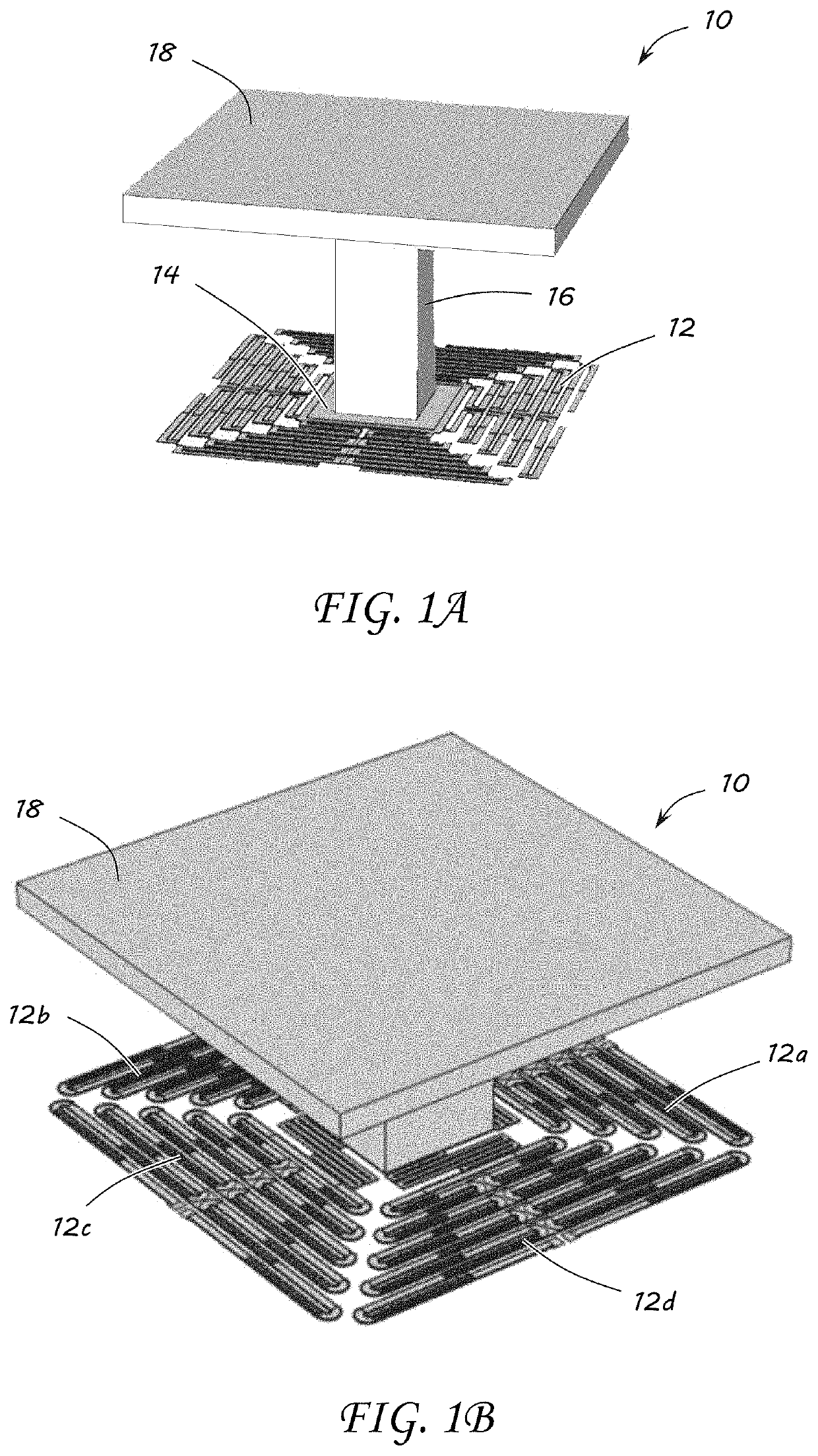
[0035]An objective of embodiments of the invention is to enable new and improved beamsteering systems with large beamsteering angles, high scanning speeds, while exhibiting high fill-factor (>90%) arrays, which may be scalable to large aperture sizes as well as enabling a multi-beam scanning capability at low voltage. Embodiments of the invention may be used to replace many gimbal based systems in a variety of applications since the devices are nearly conformal, and can eliminate nearly all large, moving mechanical parts of the scanning / detector system. Embodiments of the invention would be applicable to EO / IR beamsteering systems, medical endoscopy, imaging and scene generation systems, laser communications, and multi-target search and track. Contemporary systems use gimbal systems, which are slow, with a single beamsteering direction, and no multi-target capability. Some advantages of associated with the embodiments of the invention is it can remove most mechanical / gimbal based sy...


PUM

PropertyMeasurementUnit
anglesaaaaaaaaaa
tilt angleaaaaaaaaaa
tilt anglesaaaaaaaaaa

Abstract

An actuator element of a MEMS device on a substrate is provided to create large, out-of-plane deflection. The actuator element includes a metallic layer having a first portion contacting the substrate and a second portion having an end proximal to the first portion. A distal end is cantilevered over the substrate. A first insulating layer contacts the metallic layer on a bottom contacting surface of the second cantilevered portion from the proximal to the distal end. A second insulating layer contacts the metallic layer on a portion of a top contacting surface at the distal end. The second portion of the metallic layer is prestressed. A coefficient of thermal expansion of the first and second insulating layers is different than a coefficient of thermal expansion of the metallic layer. And, a Young's modulus of the first and second insulating layer is different than a Young's modulus of the metallic layer.

Description

CROSS-REFERENCE TO RELATED APPLICATIONS[0001]This application is a continuation-in-part of U.S. application Ser. No. 16 / 052,018, entitled “MEMS Device for Large Angle Beamsteering,”, which claims the benefit of and priority to U.S. Provisional Application Ser. No. 62 / 540,177, entitled “Post-Processing Techniques on MEMS Foundry Fabricated Devices for Large Angle Beamsteering,” filed on Aug. 2, 2017, and U.S. Provisional Application Ser. No. 62 / 587,734, entitled “Segmented Control of Electrostatically Actuated Bi-Morph Beams,” filed on Nov. 17, 2017, and U.S. Provisional Application Ser. No. 62 / 589,610, entitled “Using Surface Micromaching to Create Large Tip, Tilt, and Piston MEMS Beamsteering Structures,” filed on Nov. 22, 2017, and U.S. Provisional Application Ser. No. 62 / 667,647, entitled “Torsional Structures to Enable Large Angle Deflections,” filed on May 7, 2018, and U.S. Provisional Application Ser. No. 62 / 702,595, entitled “Torsional Springs to Enable Large Angle Tip / Tilt B...

Claims


Application Information

Patent Timeline
Patent Type & Authority Applications(United States)
IPC IPC(8): G02B26/08B81B3/00B81C1/00
CPCB81B2201/032G02B26/0866B81B2201/042B81C1/0038B81B3/0043B81B3/0037B81B2201/047B81B2203/0109B81B2203/0163B81B2203/053B81B2203/058
Inventor STARMAN, LAVERN AWALTON, JOHN PKTORRES REYES, DAVID
Owner THE UNITED STATES OF AMERICA AS REPRESETNED BY THE SEC OF THE AIR FORCE
Why Eureka
Try Eureka