Wheel bearing system with generator

a technology of generators and bearings, applied in the direction of magnetic circuit rotating parts, magnetic circuit shape/form/construction, transportation and packaging, etc., can solve the problems of high manufacturing costs, complicated structure, and less efficient motors of inner-rotor types than motors of outer-rotor types, so as to reduce costs, prevent electrolytic corrosion, and simplify the structure

Active Publication Date: 2020-04-09
NTN CORP
View PDF0 Cites 4 Cited by
  • Summary
  • Abstract
  • Description
  • Claims
  • Application Information

AI Technical Summary

Benefits of technology

[0011]An object of the present invention is to provide a wheel bearing apparatus with a generator that can have a simplified structure to reduce costs and is capable of preventing electrolytic corrosion.

Problems solved by technology

The motor of the inner-rotor type is less efficient than a motor of an outer-rotor type because a moment is generated at a position on an inner-diameter side.
In addition, since the wheel driving device of Patent Document 1 requires a speed reducer or reduction gear and the like, the device includes a greater number of components, resulting in higher manufacturing costs.
Accordingly, installation of an auxiliary power system results in a configuration of components equivalent to that of a four-wheel drive vehicle, which makes the structure complicated and causes an increase in a vehicle weight.
The spark causes the rolling element and the raceway surface to melt, resulting in a pearskin-like or corrugated electrolytic corrosion.
Occurrence of such electrolytic corrosion may generate abnormal noise from the bearing or lead to shortened life of the bearing.

Method used


Image

  • Wheel bearing system with generator
  • Wheel bearing system with generator
  • Wheel bearing system with generator

Examples


first embodiment

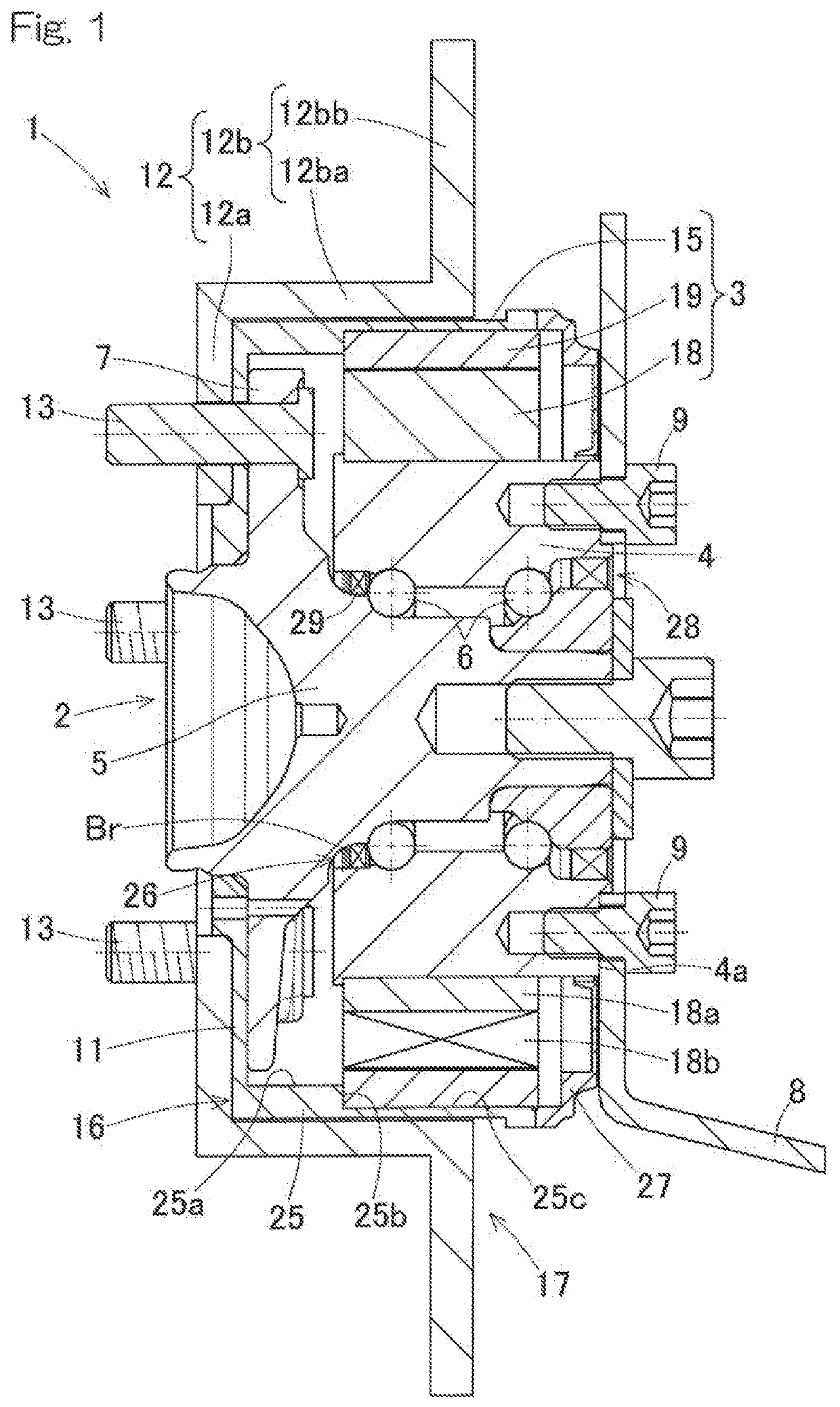
[0042]A wheel bearing apparatus with a generator according to the present invention will be described with reference to FIG. 1 and FIG. 2. As shown in FIG. 1, the wheel bearing apparatus 1 with a generator includes a wheel bearing 2 and a generator 3.

[0043]2>

[0044]The wheel bearing 2 includes an outer ring 4 as a fixed wheel, double-row rolling elements 6, and an inner ring 5 as a rotating wheel. The inner ring 5 is rotatably supported by the outer ring 4 via the double-row rolling elements 6. A bearing space between the inner and outer rings 5, 4 is filled with grease. The inner ring 5 has a hub flange 7 at a part protruding toward an outboard side in an axial direction with respect to the outer ring 4. The outer ring 4 is attached to a chassis frame part 8 (such as a knuckle) by a bolt 9 on a vehicle body attachment surface 4a, which is an end portion (on the inboard side) opposite to the hub flange 7, so as to support a weight of the vehicle. It should be noted that, in this desc...

second embodiment

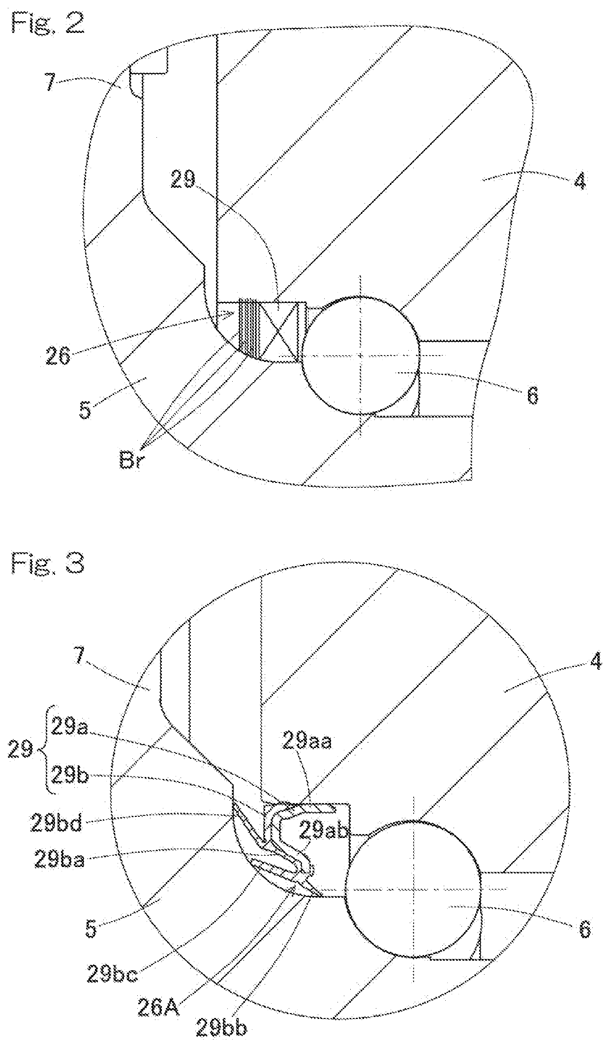
[0061]As shown in FIG. 3, in a conducting unit 26A of a wheel bearing apparatus with a generator the outer-side sealing member 29 may be made of a conductive material. That is, the outer-side sealing member 29 includes a conductive core metal 29a made of steel and a conductive elastic member 29b fixed to the core metal 29a. The core metal 29a includes a cylindrical portion 29aa and a radial wall portion 29ab extending radially inward from an outboard-side end portion of the cylindrical portion 29aa. The cylindrical portion 29aa is press-fitted with an interference fit to the inner peripheral surface of the shoulder part of the outer ring 4.

[0062]The elastic member 29b is made of, for example, a conductive rubber material. The conductive rubber material may preferably have a volume resistivity value of 30×103Ω·cm or lower. The elastic member 29b includes a sealing main body 29ba fixed to the core metal 29a and a plurality of lip portions 29bb, 29bc, 29bd extending from the sealing m...

third embodiment

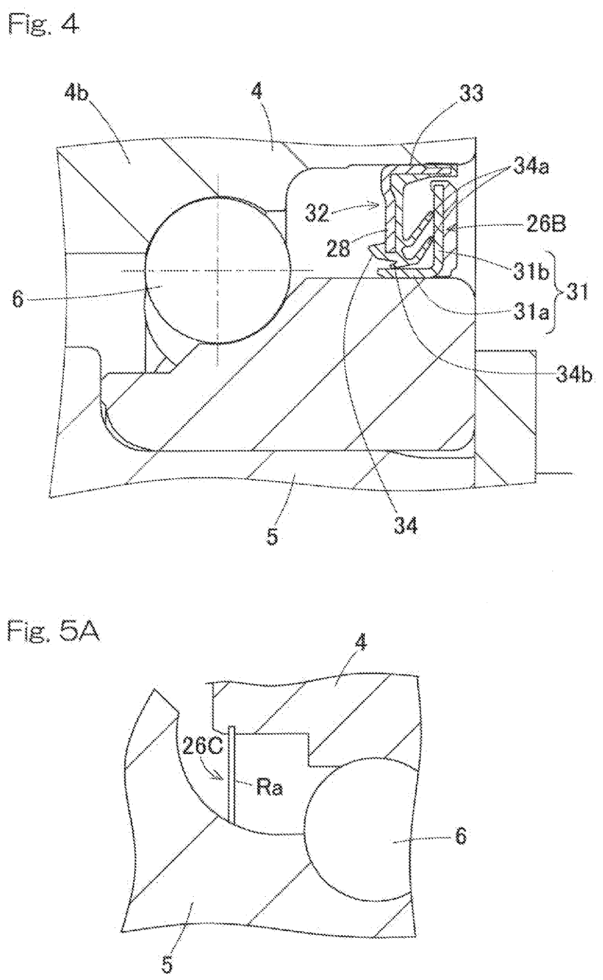
[0064]As shown in FIG. 4, in a conducting unit 26B of a wheel bearing apparatus with a generator the inner-side sealing member 28 may be made of a conductive material. In such a case, the outer-side sealing member 29 (FIG. 3) may be made of a conductive material or a non-conductive material. Specifically, where the outer-side sealing member is made of a non-conductive material, the elastic member 29 (FIG. 3) may be made of, for example, an elastic material, such as natural rubber, butadiene rubber, or nitrile rubber.

[0065]The inner-side sealing member 28 includes an annular sealing plate 31 and an annular sealing member 32 that are attached to the inner ring 5 and the outer ring 4, respectively, so as to face each other. The sealing plate 31 is made of steel, which is conductive. The sealing plate 31 includes a cylindrical wall portion 31a fitted to the outer peripheral surface of the inner ring 5 and a radial wall portion 31b extending upward from an inboard-side end portion of th...


PUM


Abstract

Provided is a wheel bearing apparatus with a generator that can have a simplified structure to reduce costs and is capable of preventing electrolytic corrosion. The wheel bearing apparatus with a generator includes a wheel bearing and a generator. The generator includes a stator attached to a fixed wheel and a motor rotor attached to a rotating wheel and is of an outer-rotor type in which the stator is located on an outer periphery of the wheel bearing, and the motor rotor is located radially outside of the stator. The wheel bearing apparatus with the generator further includes at least one conducting unit that conducts a current between the fixed wheel and the rotating wheel.

Description

CROSS REFERENCE TO THE RELATED APPLICATION[0001]This application is a continuation application, under 35 U.S.C. § 111(a), of international application No. PCT / JP2018 / 021413, filed Jun. 4, 2018, which claims Convention priority to Japanese patent application No. 2017-113246, filed Jun. 8, 2017, the entire disclosures of all of which are herein incorporated by reference as a part of this application.BACKGROUND OF THE INVENTIONField of the Invention[0002]The present invention relates to a wheel bearing system or apparatus with a generator and to a technology of simplifying a structure to reduce costs and preventing electrolytic corrosion.Description of Related Art[0003]A wheel driving device having a motor of an inner-rotor type as a driving source has been proposed (Patent Document 1). In such a wheel driving device, a contacting body having a conical surface or a spherical surface and electrically connected with a stator is pressed against a rotor so as to achieve electrical conducti...

Claims


Application Information

Patent Timeline
Patent Type & Authority Applications(United States)
IPC IPC(8): H02K7/18B60B27/00H02K1/27F16C41/00
CPCH02K7/1861B60B27/0094B60B27/0005F16C2300/42F16C41/004H02K1/2786F16C41/002F16C19/186B60K7/0007F16C33/7876B60K2007/0038B60K2007/0092H02K1/2791
Inventor YABUTA, HIROKIKAWAMURA, MITSUONISHIKAWA, KENTARO
Owner NTN CORP
Why Eureka
Try Eureka