Valve control device, cooling device, and valve control method
- Summary
- Abstract
- Description
- Claims
- Application Information
AI Technical Summary
Benefits of technology
Problems solved by technology
Method used
Image

Examples
first example embodiment
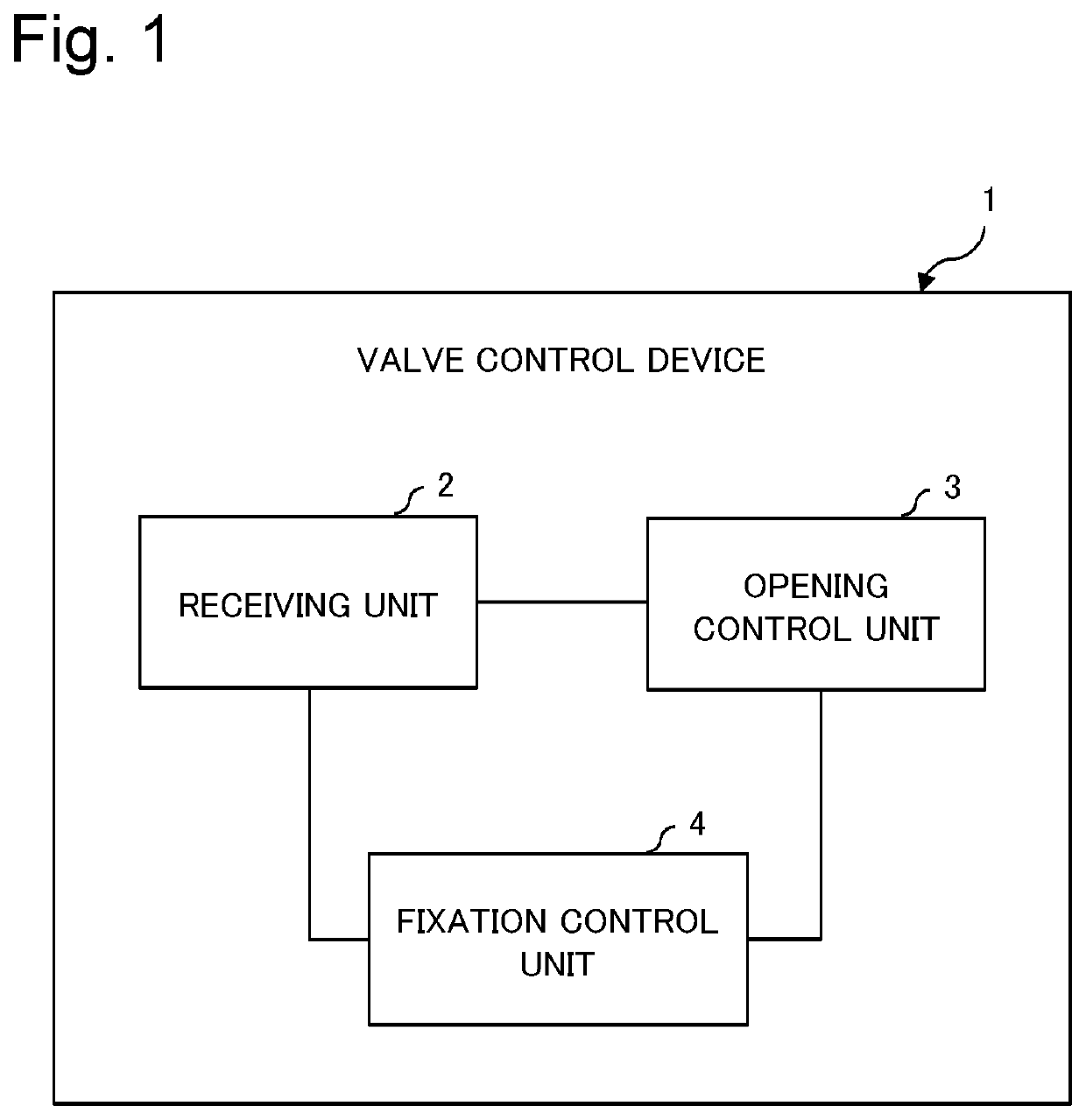
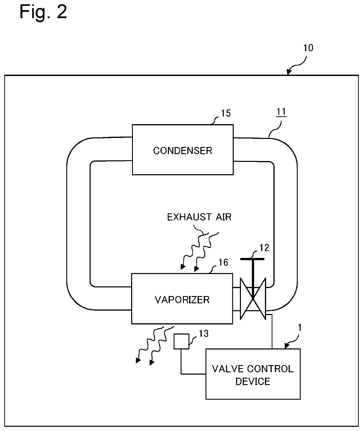
[0040]FIG. 1 is a block diagram illustrating a functional configuration of a valve control device according to a first example embodiment of the present invention. FIG. 2 is a diagram illustrating a configuration of a cooling device incorporating the valve control device according to the first example embodiment.
[0041]A valve control device 1 according to the first example embodiment is a device that controls a valve 12 included in a cooling device 10 illustrated in FIG. 2. Specifically, the cooling device 10 includes a circuit 11 of refrigerant, the valve 12, and a thermometer 13.
[0042]The circuit 11 is a flow path through which a refrigerant is circulated. A vaporizer 16 and a condenser 15 are provided along the circuit 11. The vaporizer 16 is a part that cools a fluid to be cooled through exchange of heat between the fluid to be cooled (e.g., exhaust air that absorbs heat from an electronic device to cool the electronic device) and a refrigerant. The condenser 15 is a part in whi...
second example embodiment
[0047]A second example embodiment according to the present invention will be described below.
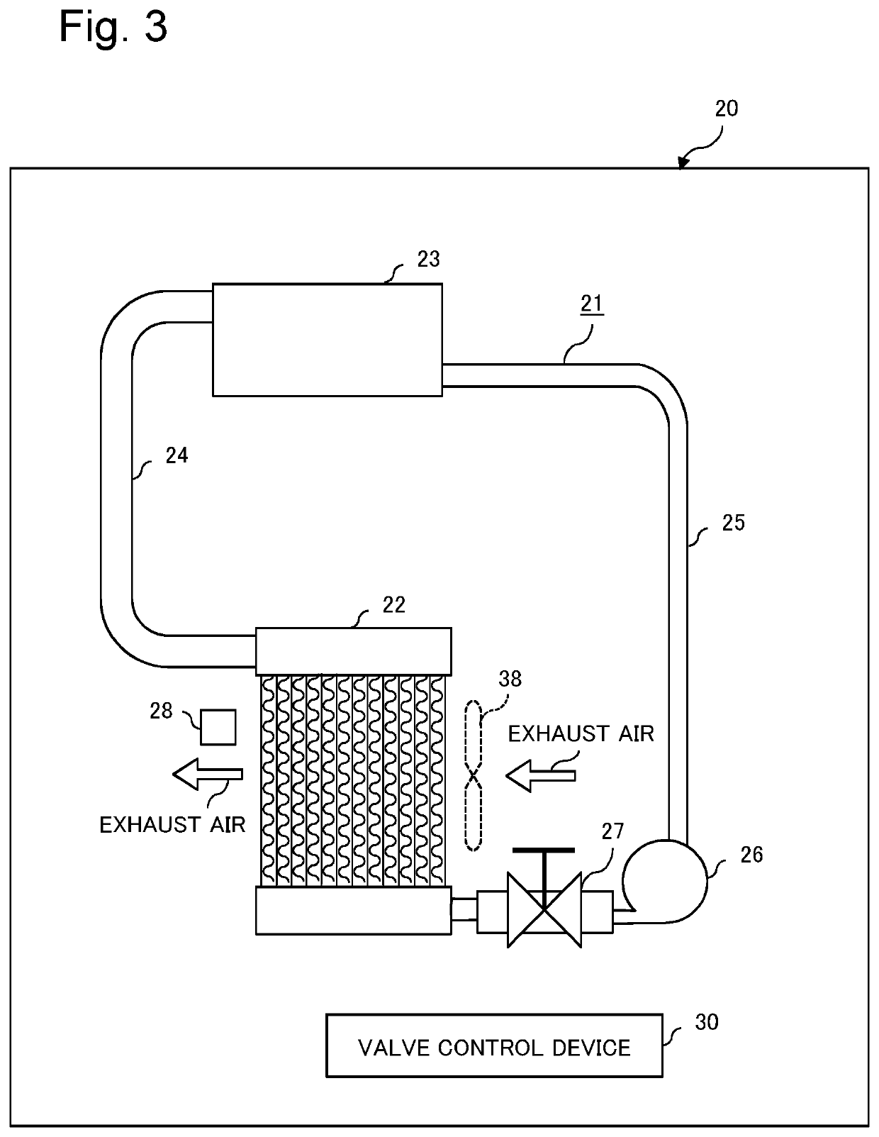
[0048]FIG. 3 is a diagram illustrating a configuration of a cooling device including a valve control device according to the second example embodiment. A cooling device 20 is a phase-change cooling device, and includes a heat receiving unit 22 serving as a vaporizer, a radiation unit 23 serving as a condenser, a vapor passage 24, a liquid passage 25, a refrigerant pump 26, a valve 27, and a thermometer 28. The cooling device 20 further includes a valve control device 30.
[0049]The heat receiving unit 22 is disposed, for example, at an exhaust air side of a storage body (not illustrated) of an electronic device. The electronic device generates a high calorific value and is such as a server. Specifically, in the storage body of the electronic device, air suction and exhaust is performed by rotationally driving a fan 38, and an air (exhaust air) from which heat emitted from the electronic device...
third example embodiment
[0089]A third example embodiment according to the present invention will be described below. Note that in the description of the third example embodiment, parts having the same name as that of constituent parts constituting the cooling device according to the second example embodiment are denoted by the same reference numerals, and repeated explanations of the same parts are omitted.
[0090]FIG. 6 is an explanatory diagram illustrating a configuration of a cooling device according to the third example embodiment in a simplified manner. A cooling device 20 according to the third example embodiment includes a plurality of heat receiving units 22a to 22c. Further, a liquid passage 25 is branched into branch passages 40a to 40c on a side that is closer to the radiation unit than the refrigerant pump 26. The branch passages 40a to 40c communicate with and are connected to the heat receiving units 22a to 22c respectively. Valves 27a to 27c are provided along the branch passages 40a to 40c, ...
PUM
 Abstract
Description
Claims
Application Information
 - R&D
- Intellectual Property
- Life Sciences
- Materials
- Tech Scout
- Unparalleled Data Quality
- Higher Quality Content
- 60% Fewer Hallucinations
Browse by: Latest US Patents, China's latest patents, Technical Efficacy Thesaurus, Application Domain, Technology Topic, Popular Technical Reports.
© 2025 PatSnap. All rights reserved.Legal|Privacy policy|Modern Slavery Act Transparency Statement|Sitemap|About US| Contact US: help@patsnap.com